HOW TO MAKE A 1/6th Scale Room
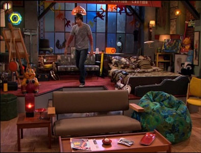
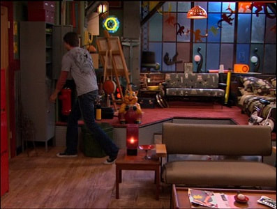
…in this case, a bedroom resembling the one used by Spencer Shay on Nickelodeon’s iCarly.
All of my sets are built upon the same principles as this room aside from my TARDIS console room set which is quite a bit OLDER...and cruder...but still very functional.
Based primarily on these two screen captures, as well as watching several episodes featuring it, I guessed off lengths, widths and heights of the room as well as the elevated area.
|
|
I had a few new ideas as this was to now be the grown up Carly Shay’s bedroom…she would have a nicer bed and other furniture. Just a lot more girlie looking. But the basics of the room should be undeniable regarding general layout and that massive window on the back wall.
PARTS LIST
¾” pine lumber (1” x 6” or 1” x 8”) door, door frame, wall & elevation framing
Luon sheet (3/16” plywood) walls & elevation flooring, door panels
¾” x 1/16” aluminum stock side wall bottoms (2)
7/16” brass rod door knobs (2)
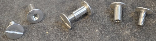
Screw Post with Bolt (14) to hold window to back wall
Clear window replacement plastic for window
Cloth for curtains
5/32” Hobby Tube for curtain rod
Misc screws, ½”-5/8” brads, glue
Paint
Picture of stamped metal sheeting(optional) for vertical surfaces of elevated area
The final room worked out to 3 feet wide (or 18 feet in 1/6th scale) x 32” (or 16 feet in 1/6th scale)
¾” pine lumber (1” x 6” or 1” x 8”) door, door frame, wall & elevation framing
Luon sheet (3/16” plywood) walls & elevation flooring, door panels
¾” x 1/16” aluminum stock side wall bottoms (2)
7/16” brass rod door knobs (2)
Screw Post with Bolt (14) to hold window to back wall
Clear window replacement plastic for window
Cloth for curtains
5/32” Hobby Tube for curtain rod
Misc screws, ½”-5/8” brads, glue
Paint
Picture of stamped metal sheeting(optional) for vertical surfaces of elevated area
The final room worked out to 3 feet wide (or 18 feet in 1/6th scale) x 32” (or 16 feet in 1/6th scale)
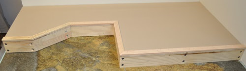
BUILDING THE ELEVATED AREA
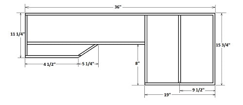
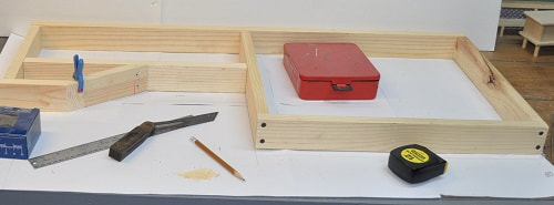
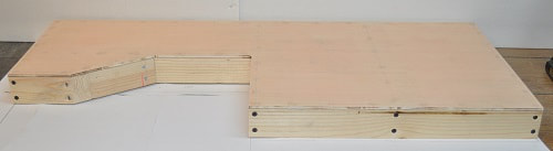
I started the build with the elevated floor as all three walls will be wrapped around it. As I was using 3/16 Luon (thin plywood used for underlayment), I cut enough ¾” thick pine boards to 2 1/8” wide and laid out the framework. The sketch below shows the measurements used. Note: The sketch is NOT to scale.
I started the build with the elevated floor as all three walls will be wrapped around it. As I was using 3/16 Luon (thin plywood used for underlayment), I cut enough ¾” thick pine boards to 2 1/8” wide and laid out the framework. The sketch below shows the measurements used. Note: The sketch is NOT to scale.
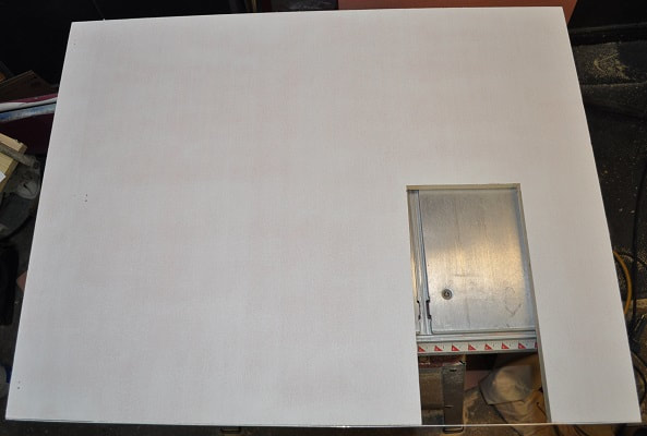
The next step is to cover the top side with Luon. I cut mine a little oversized by a good 1/8”. Next, glue and nail it in place, using ½”-5/8” brads (countersinking them and filling with plastic wood to be sanded later), with minimal overhang on all sides, then I used a router with a bit made for Formica to bring the edges of the Luon down even with the frame. This gave a nice clean edge all around for attaching the edge surface material later. The only issue is the one inside 90 degree angle, which had to be hand sanded down.
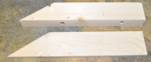
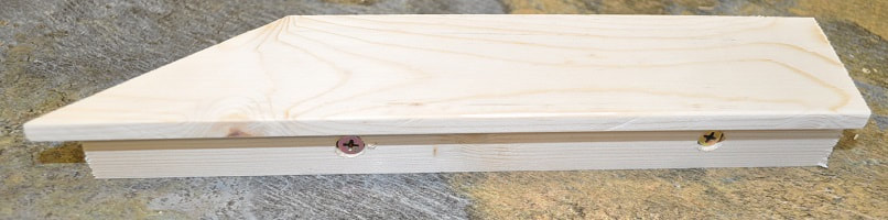
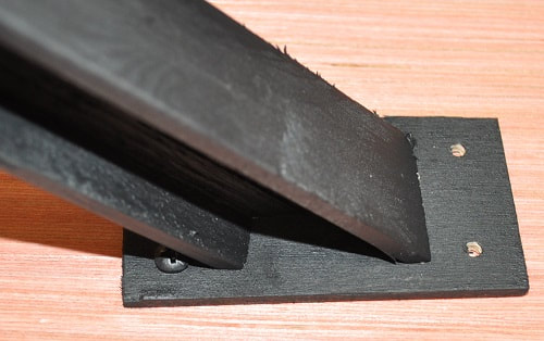
The single step can be fabricated now. Unlike the living room step, this one is not open but rather a closed up box with an overhanging tread. I made the bottom from an old 2 x 4 scrap and the top from a scrap of pine planed down to about .300” thick. While the one end is a 90 degree angle, the other needs custom fit. I drilled two holes for two screws that, with their holes counter-bored a good ¾”, would stick out the back about ¾” to secure it.
|
|
Step Parts Assembled step waiting steel plating
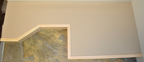
Paint the top surface the color of your choice. After another trip to the lumberyard to look through their selection of 18” tile squares, I chose eight tiles for the floor (four are for the bedroom and four are for the master bathroom) that had a nice beige as one of its many colors which allowed me to use the beige I used on the walls of many of my other sets for this floor.
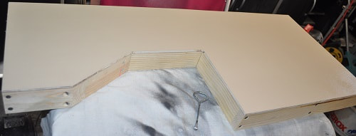
With the single step fabricated and ready to be installed and the top surface painted and dry, it is time to add the trim molding around the top, front edge. Rip enough strips of ¾” wide board to 3/16” thick for the front edges. Cut the corners so they fit with a 1/16” to 1/8” overhang. This is what will hide the top edge of the metal plating to be added in a moment. These strips should be fastened down with ½” – ¾” brads, the heads should be set, filled and sanded. I left mine unfinished as I did in the living room.
|
|
Now to finally address the other surfaces. The vertical surfaces of this elevated area are shown as stamped out metal sheets. I made my covering by locating online a nice picture of this sheet that I printed out on card stock, added two-sided tape to the back, cut to the correct width with a razor blade and carefully applied to each surface. My printouts are at most 10 5/8” long so the very front surface must be at least two pieces. Cut the material squarely and do your best to butt the joint together tightly.
The width required is from the bottom to the top of the vertical faces. The top edge, as stated, is hidden by the trim pieces. Test fit each piece before removing the paper from the tape surface. Then carefully apply each piece. If any part sticks out below the bottom…trim it off with a razor blade. For this project, I suggest starting at the inner 90 degree angle and work out from it as it is an absolute. Unlike the other smaller angles that can be more easily wrapped to fit well.
The width required is from the bottom to the top of the vertical faces. The top edge, as stated, is hidden by the trim pieces. Test fit each piece before removing the paper from the tape surface. Then carefully apply each piece. If any part sticks out below the bottom…trim it off with a razor blade. For this project, I suggest starting at the inner 90 degree angle and work out from it as it is an absolute. Unlike the other smaller angles that can be more easily wrapped to fit well.
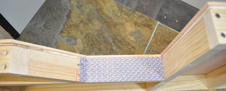
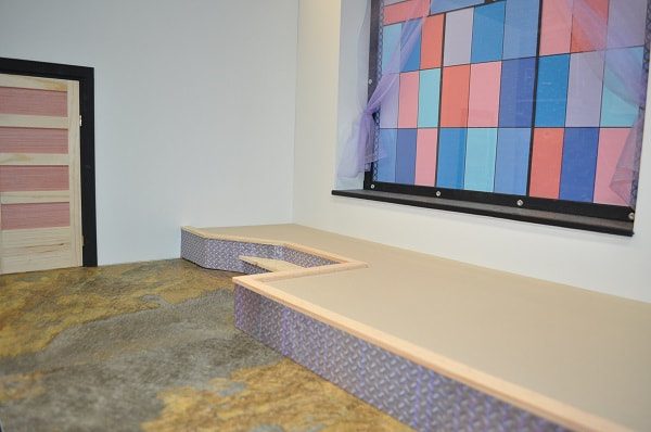
One steel panel in place.
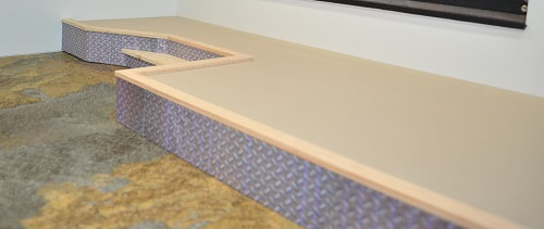
All steel panels in place with the step secured.
With all the metal plating in place, now attach the single step with the two screws. Apply the final strip of metal plating to the front of the single step.
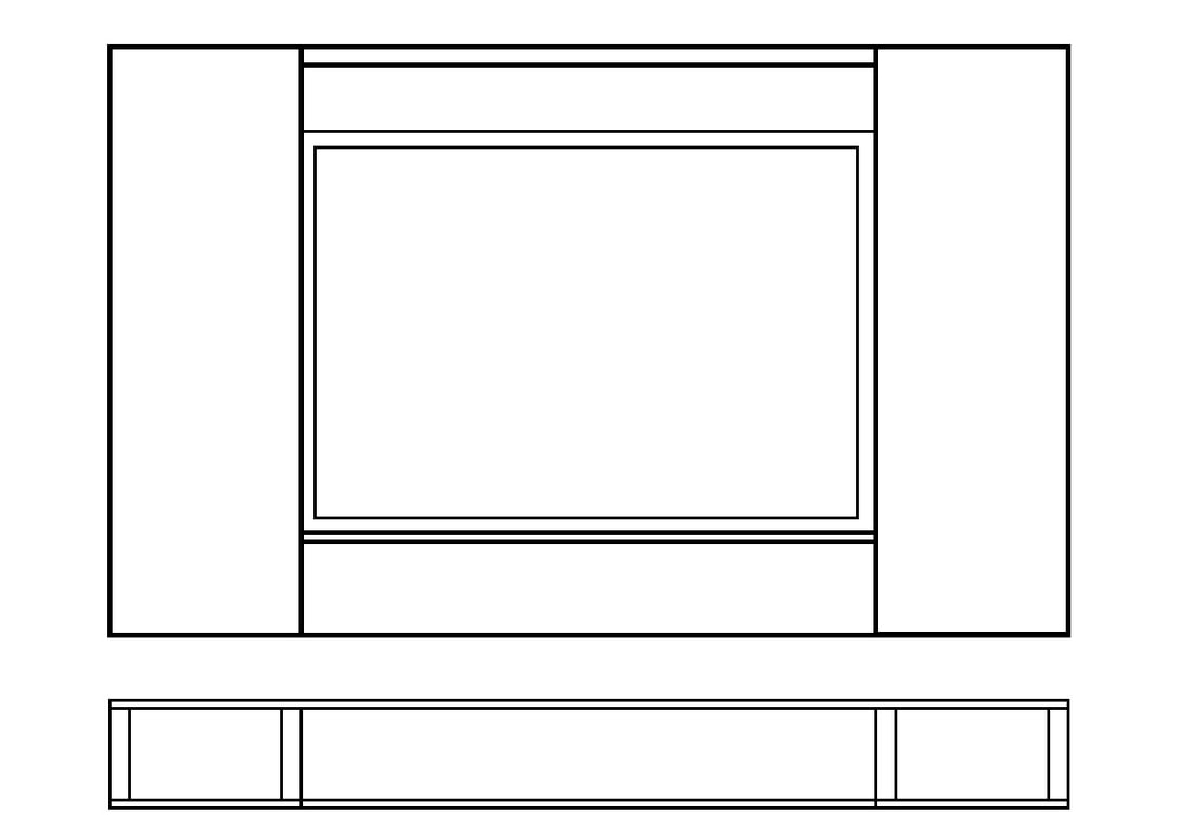
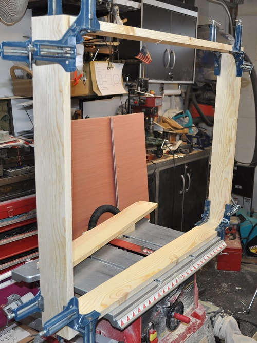
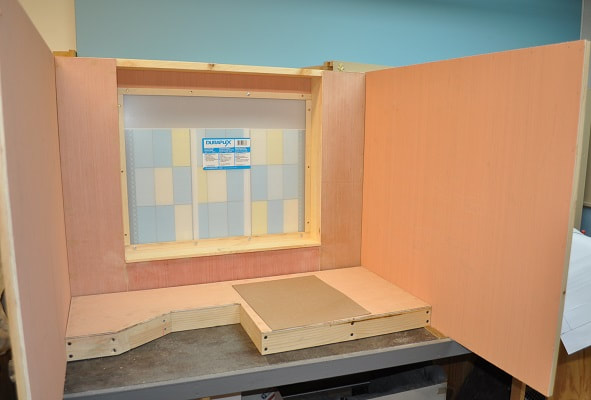
Now that the elevated area is structurally completed, it is now time for the back wall. I cut a piece of Luon to 36” wide by 28” (as 28” is the overall height of all my walls.) I like to have side walls attach with screws from the side…not the back…as I often remove one or the other for that certain otherwise unattainable shot. Also, as this wall will have a stout frame around it made up of 6” wide boxes, the 3 ½” wide ledge between them at the floor and a board across the top to hook the 45 degree girders to, the plan is to make the remainder of the wall single thickness Luon as this area will also be taken up by that massive window. Most of my walls are two sheets of Luon with a .400 framework of wood in the center. With the Luon cut to size, next up is the 6” x 3” boxes for each side and the very top and bottom boards of this framework. The top and bottom boards are ¾” pine as are both sides of the boxes. The larger side of these boxes and the area below the ledge are Luon.
|
|
This wall starts out as a simple frame made from 1 x 8 material cut in half. I was surprised to learn that 1 x 8’s are no longer 7 ½” wide. They are now 7 ¼” wide. Go figure.
Once the frame was screwed together, I added a board of the same width vertically 6” from each end. That left the 24” I wanted for the massive window between them. The wide window ledge is made from a piece of material 3/8” wider than the frame so it would stick out into the room 3/16” after adding the Luon facing. I cut a 3/8” x 3/8” notch in the bottom edge to make this board look thinner. This also gave me a place to nail the bottom piece of Luon. This board was mounted horizontally between the uprights so the top surface is 6” from the bottom. So, with the height of the elevated area subtracted from the 6”, this ledge will be about 22” (in 1/6th scale) high. Comfortable for sitting. The front corner also has a nice radius on it. Glue and nail the three Luon pieces in place. Set the nails below the surface, fill with plastic wood and sand as needed. Hopefully between the sketch and the pictures above you can see how this wall is taking shape.
Next up…the window.
Next up…the window.
FABRICATION OF THE STAINED GLASS WINDOW
I cheat a great deal on these windows. Following the same technique I used in the LOFT/STUDIO set and the living room set, this amounts to nothing more than several computer printouts trimmed and taped together, trapped between the wall and a sheet of .080” plastic window replacement material from the local lumber yard. (This time I secured the assembled printout to a sheet of poster board just to make it easier to handle.) All held in place by a wooden framework that we will talk about next. Getting everything to fit in the needed pictures can be tricky though…plus the limitations of a computer printer.
I cheat a great deal on these windows. Following the same technique I used in the LOFT/STUDIO set and the living room set, this amounts to nothing more than several computer printouts trimmed and taped together, trapped between the wall and a sheet of .080” plastic window replacement material from the local lumber yard. (This time I secured the assembled printout to a sheet of poster board just to make it easier to handle.) All held in place by a wooden framework that we will talk about next. Getting everything to fit in the needed pictures can be tricky though…plus the limitations of a computer printer.
The window frame…
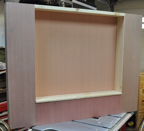
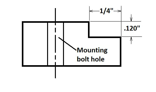
Cutting strips from a ¾” thick board just over ¼” thick that are long enough as I need two at 24” for the top and bottom and 2 at 17 ½” for the sides, I ran them through my planer to clean up the sides. Leaving them a little long may be a good idea. Again, I set up my mill table with a stop to slide these pieces against to add a recess to one corner to accept the plastic and the printout. The thickness of my printout, the plastic sheet and the poster board equaled about .105”. This should be the target for the depth of the recess to + .010. These recesses should be ¼” deep the other way. See the sketch below for an end view.
Cutting strips from a ¾” thick board just over ¼” thick that are long enough as I need two at 24” for the top and bottom and 2 at 17 ½” for the sides, I ran them through my planer to clean up the sides. Leaving them a little long may be a good idea. Again, I set up my mill table with a stop to slide these pieces against to add a recess to one corner to accept the plastic and the printout. The thickness of my printout, the plastic sheet and the poster board equaled about .105”. This should be the target for the depth of the recess to + .010. These recesses should be ¼” deep the other way. See the sketch below for an end view.
|

|
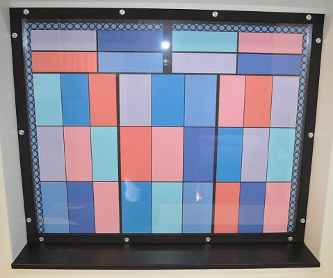
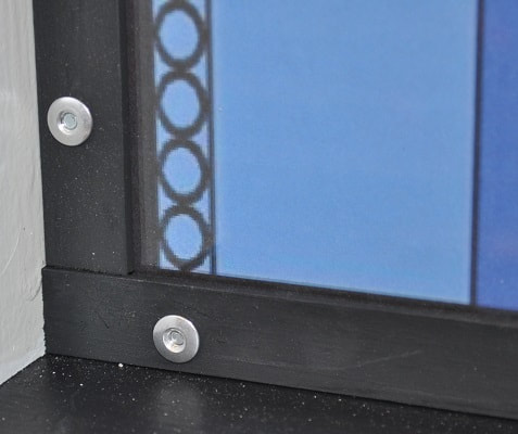
Again, like on my loft/studio and living room sets, I used several (14), what is termed on the package as, SCREW POST WITH BOLT from a local lumber yard to secure the frame to the back wall as they fit the architecture. Three on each side and four on top and bottom as shown. Putting the screwdriver slot on the backside of the wall leaves the RIVET looking part in the window frame and I like the way they look.
Now remove the window and window trim. Do any final sanding and start priming and painting. I like to roll on a good primer to these surfaces as it hides the wood grain very nicely so it does not show through in the final color. As in the living room, I simply painted the window frame a flat black as this sets off the silver of the bolts nicely.
Now remove the window and window trim. Do any final sanding and start priming and painting. I like to roll on a good primer to these surfaces as it hides the wood grain very nicely so it does not show through in the final color. As in the living room, I simply painted the window frame a flat black as this sets off the silver of the bolts nicely.
|
|
Finished Window Window corner detail
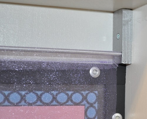
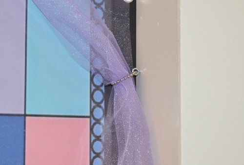
With the window now in place, I wanted some sort of curtain system. Had I known exactly what I wanted I would have predrilled the holes for the curtain rod but, as I didn’t know, I made two small brackets from some scrap wood, sanded and primed them well enough and painted them with an “aluminum” color paint to more match the 5/32” aluminum rod (tube actually) and also make it so I did not have to paint the head of the screw holding it in place.
|
|
|
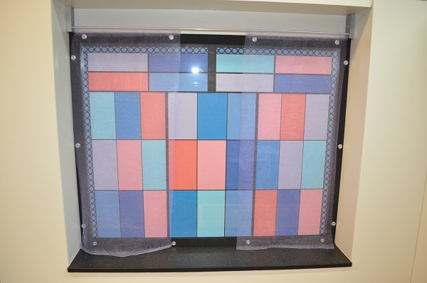
Curtain rod bracket Curtain Tie-Back Finished Sheer Curtains
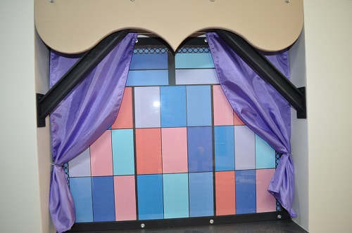
I chose to use the same sheer material I used for the bed curtains from the canopy bed but may change these to the solid, satin material used for the sheets. We’ll have to wait and see.
The sheer curtains, after applying the top hem, measured 9” wide and 19 ½” long. To span the full window, they would each have to be at least 11 ½” wide. The curtain tie-backs amount to a very small eye-screw and a length of silver bead chain.
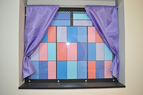
While I was at this point, I fabricated a pair of solid violet curtains from the scrap used for the canopy bed sheets. They are near enough identical in size to the sheer ones. Still undecided on which set I like the best. But here they are.
The sheer curtains, after applying the top hem, measured 9” wide and 19 ½” long. To span the full window, they would each have to be at least 11 ½” wide. The curtain tie-backs amount to a very small eye-screw and a length of silver bead chain.
While I was at this point, I fabricated a pair of solid violet curtains from the scrap used for the canopy bed sheets. They are near enough identical in size to the sheer ones. Still undecided on which set I like the best. But here they are.
VALANCE FABRICATION
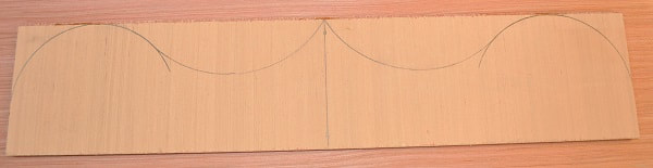
With the working curtains in place, I added the valance across the whole of the top window section by cutting two pieces of Luon 24” wide with one at 5” wide and the other 4 ¼” wide. I glued these two pieces together so the missing ¾” on the one was all at one side. I then drew the final curvature to the other edge as shown below.
With the working curtains in place, I added the valance across the whole of the top window section by cutting two pieces of Luon 24” wide with one at 5” wide and the other 4 ¼” wide. I glued these two pieces together so the missing ¾” on the one was all at one side. I then drew the final curvature to the other edge as shown below.
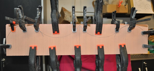
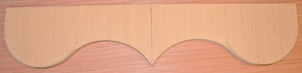
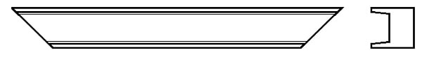
After cutting it out on a scroll saw, I sanded the edges to make the curvature flow as smoothly from one curve to the next. By making it this way…double thickness…the outer surface will set flush with the side areas yet be thick enough that I can add a 1/8” radius to the edge to dress it up a bit.
|
|
With the routering done to the bottom, outside surface only, I gave it a light sanding and a coat of primer. I then mounted it in place with four equally spaced, wood screws as I wanted this removable…not permanently mounted.
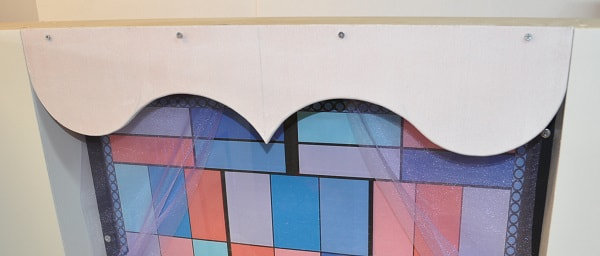
Once happy with the fit and look, next up was to remove it and apply the final paint. I was thinking this valance should be the same color beige as the elevated floor to add more color. Once the paint is fully dry it can be mounted again or set aside for adding the massive “I”-beams by the window.
I-BEAM CONSTRUCTION AND MOUNTING
There are actually several structurally supportive I-beams in the set but I only chose to include the two by the window. As it will be impossible to take a picture that will show the back of the beam, I did not recess out the back side. Only the front. On a 1 1/8” square section of scrap 2 x 4, I set my table saw blade to a slight angle…2-4 degrees…and at a depth 1/8” from the centerline and started removing the material from the material starting near the middle. Turn the part end for end and run it through again. Move the rip fence a heavy 1/16” towards the blade and run it through twice again. Repeat this until you have what looks like a one sided I-beam. Cut the material in half with a 45 degree angle on each end to fit to the walls. My beams ended up being 13 ½” long from outer end point to outer end point. By not cutting out the back side of the beam there is a LOT more material for attaching to the plywood mounting plates.
There are actually several structurally supportive I-beams in the set but I only chose to include the two by the window. As it will be impossible to take a picture that will show the back of the beam, I did not recess out the back side. Only the front. On a 1 1/8” square section of scrap 2 x 4, I set my table saw blade to a slight angle…2-4 degrees…and at a depth 1/8” from the centerline and started removing the material from the material starting near the middle. Turn the part end for end and run it through again. Move the rip fence a heavy 1/16” towards the blade and run it through twice again. Repeat this until you have what looks like a one sided I-beam. Cut the material in half with a 45 degree angle on each end to fit to the walls. My beams ended up being 13 ½” long from outer end point to outer end point. By not cutting out the back side of the beam there is a LOT more material for attaching to the plywood mounting plates.
I-Beam Sketch
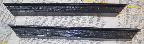
I-beams primed and drying
I cut four pieces of 1/8” hobby plywood to 1 9/16” x 2 15/16” to be mounted to the ends of the I-beams that will be screwed to the walls. I went ahead and primed the beams but tried not to get much primer on the ends.
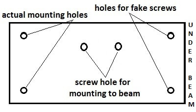
Mounting these plates to the beam is very straight forward by using two #4 or smaller x ¾” flat head wood screws through the center holes.
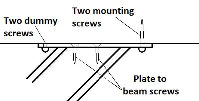
This next part is a bit trickier as you cannot get to the two screws that are inside the 45 degrees with a screwdriver. To get around this issue, the top two screws end up as “dummy screws”. I used sheet metal screws for the four corner screws so the threads went all the way to the head. This is critical for the dummy screws. Screw two screws into the “top” holes (or the holes that will be nearest the corner of the window), making sure the holes are pilot hole size so the screws hold well in the 1/8” plywood. Take a cutoff tool, like a Dremel, to cut off these screws where they stick through until they are flush or below the back surface. The only screws that will be holding the beam in place will be the two near the point of the beam.
This next part is a bit trickier as you cannot get to the two screws that are inside the 45 degrees with a screwdriver. To get around this issue, the top two screws end up as “dummy screws”. I used sheet metal screws for the four corner screws so the threads went all the way to the head. This is critical for the dummy screws. Screw two screws into the “top” holes (or the holes that will be nearest the corner of the window), making sure the holes are pilot hole size so the screws hold well in the 1/8” plywood. Take a cutoff tool, like a Dremel, to cut off these screws where they stick through until they are flush or below the back surface. The only screws that will be holding the beam in place will be the two near the point of the beam.
With a mounting plate secured to both ends of both beams, check the fit to the walls. If there is an issue…NOW is the time to address it if your beam end cuts are off. Make any adjustments to the ends so the mounting plates set VERY true to the walls. I find this next part easier to do with the wall upside down. Place each beam, in turn, in the corner of the window area and drill pilot holes for the four mounting screws and secure each beam in place. NOTE: If you are going to fashion a valance as I did, described below, you will need to ensure that the beam mounting plates are at least 3/16” – ¼” from the front of this wall as you need this room for valance clearance. With the wall being upside down, they tend to stay where you put them. Once you are happy with how they are mounted…remove them and now paint the mounting plates and touch any issues on the I-beams. Don’t forget to paint all bolt heads flat black.
|
|
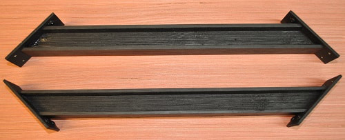
Both beams with final paint, drying Close-up of beam mounting plate
When they are fully dry, mount them back on the wall, turn the wall back over and reinstall the finished valance.
SIDE WALL CONSTRUCTION
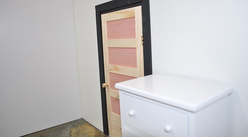
The two side walls are rather straight forward but with a door. My wall are typically .750” thick…especially when they require a door frame. The wall itself is made up of two panels of Luon with a framework of .400” wood strips making up the difference. Before starting these walls…or during their early construction…I’d suggest getting the two doors and door frames completed to help in laying out the framework. Please see my tutorial on building a wooden door for my method. On any walls that have a door in them, I run a strip of 3/4” wide x 1/16” aluminum along the bottom edge with #4 x ¾” flat head screws going into the bottom of the door frame and the wall to ensure the wall stays straight which could affect the function of the door. Plus the silver of the aluminum makes a nice threshold. Watch that these screws are properly countersunk and the holes deburred to prevent the wall from scratching whatever you use for a floor.
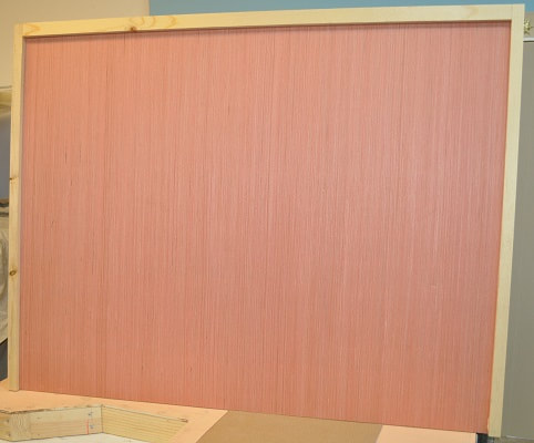
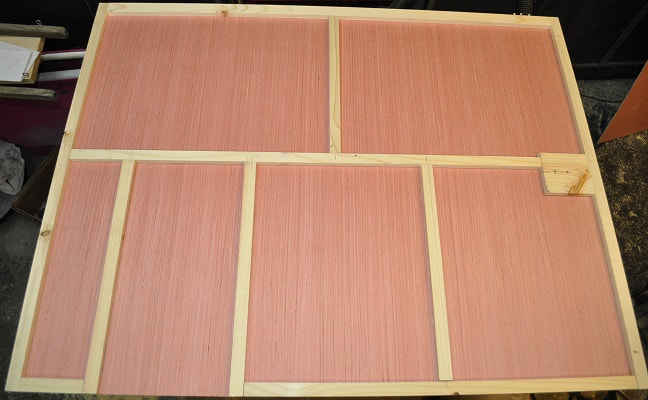
I made the two side walls both 3 feet long as well, but as they overlap the back wall by about 4” that shortens what you see to 32” or 16’ in full scale, as mentioned earlier. So this room will be equal to a 16' x 18' room. I went ahead and cut four 28” tall panels to the needed three feet. One panel for each side of my new walls. Adding a .400” thick strip of wood to the top and both sides of two panels starts the framework.
The two side walls are rather straight forward but with a door. My wall are typically .750” thick…especially when they require a door frame. The wall itself is made up of two panels of Luon with a framework of .400” wood strips making up the difference. Before starting these walls…or during their early construction…I’d suggest getting the two doors and door frames completed to help in laying out the framework. Please see my tutorial on building a wooden door for my method. On any walls that have a door in them, I run a strip of 3/4” wide x 1/16” aluminum along the bottom edge with #4 x ¾” flat head screws going into the bottom of the door frame and the wall to ensure the wall stays straight which could affect the function of the door. Plus the silver of the aluminum makes a nice threshold. Watch that these screws are properly countersunk and the holes deburred to prevent the wall from scratching whatever you use for a floor.
I made the two side walls both 3 feet long as well, but as they overlap the back wall by about 4” that shortens what you see to 32” or 16’ in full scale, as mentioned earlier. So this room will be equal to a 16' x 18' room. I went ahead and cut four 28” tall panels to the needed three feet. One panel for each side of my new walls. Adding a .400” thick strip of wood to the top and both sides of two panels starts the framework.
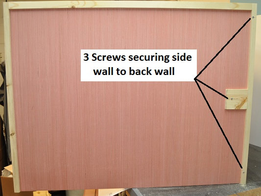
I plan to use three 1 ½” #6 flat head screws to attach each wall to the back wall. NOTE: For storage of these three screws when the wall is not in use, I typically drill three pilot holes in the top .400 filler strip near one corner and run the screws into these holes with a cordless drill for storage. It beats looking for three more screws every time you want to use it. When in use, two go through the edge framework but the third needs a filler piece of wood where it will go through the wall for strength. Before drilling your pilot holes into the end window wall for these screws be sure to place the ¾” x 1/16” aluminum strip under each wall as this will be added later and will throw your holes off if you don’t. Getting these both secured to the back wall before adding the other sheet of Luon makes it simpler to ensure the screws ARE going through what you want them to.
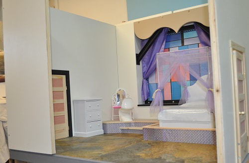
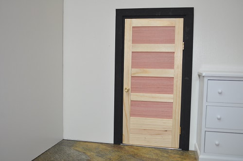
Here you can see both walls attached to the back wall with the elevated area between them. This is a good time to decide just where you want the two doors. One for the entry back into the living room and one for the master bathroom, which I am putting roughly opposite the main door. Note: The piece of cardboard on the elevated area is approximately the size of the new bed.
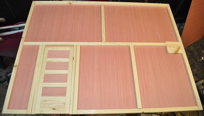
Once you have marked the walls for the rough door locations, remove both walls from the back wall and finish framing them in. Notice the chosen area for the door is not framed in at the bottom. I make these openings about 1/16” too wide and at least a 1/16”, but not more than 1/8” too tall for the door jamb.
I use a saber saw to remove the material where the door will go. You can clean up this opening with a router and a bit designed to finish the edge of Formica if you like but it is not necessary. But I do it just to make working with it and fitting the jamb properly easier.
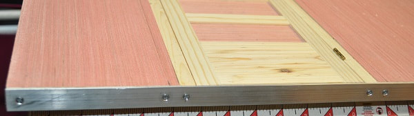
Set the door and jamb aside and attach the other panel of Luon to the wall with glue and ½” brads using care just where the internal framing is when driving the brads. Drill through from the inside wall surface for the three wood screws that will hold each wall to the back wall. Again, use a saber saw to remove the Luon where the door will go and clean up the edges if you like. Place the wall on a flat surface with the bedroom wall side up. Place the door in the opening. Check it for fit. You should be able to hold it in place with equal spacing around the door and open and close it easily. Watch that this opening IS square. If all looks good, add the strip of ¾” x 1/16” aluminum to the bottom edge with #4 x ¾” flat head wood screws. You can see I have one screw near the door opening and another screw in the bottom of each door jamb. This strip keeps the wall from ever twisting or springing due to having the door in it.
Remove the two screws in the door jamb and set the door aside. They will be permanently installed after painting the wall. If your wall, door jamb and trim are to be painted the same color, they CAN be installed now but should still be SPRAY painted…not brush painted as brush painting is much thicker and may interfere with opening. (SEE DOOR INSTALLATION) All that is left to do before priming and painting is to set all brads in the Luon below the surface, fill them all with plastic wood and give both sides a good but gentle sanding.
With all nail holes filled and all surfaces sanded and wiped down, roll on a GOOD primer, like KILZ. As I’ve mentioned before, using a good primer does wonders to hide wood grain when you do not want it to be seen and gives the walls a nice gently bumpy surface that I like.
With all nail holes filled and all surfaces sanded and wiped down, roll on a GOOD primer, like KILZ. As I’ve mentioned before, using a good primer does wonders to hide wood grain when you do not want it to be seen and gives the walls a nice gently bumpy surface that I like.
Once this is dry, roll on your final color choice. For this room, for now, I am going with a bright white. I may regret it later but I feel white will go better with the planned furnishings and window treatments. So there will not be much difference in color my pictures from priming to painting. Just that painted surfaces will be more uniform in the “white.”
INSTALLING DOORS AND JAMBS
(this is also covered in Building a Wooden Door Tutorial)
I painted the jamb and trim of the main door flat black to match the door scheme in the living room set that leads to this bedroom while others are left natural. With the two screws in the bottom of the door jamb, it takes little to hold it in place. The jamb trim is enough to hold it in if you like. Or you can drill a single through hole in the header of the jamb and install a single brad prior to adding the trim molding. If you DO drill a hole for a brad, be sure to drill a larger diameter at the start of the hole for the brad head…or nip off the head altogether before driving it in flush with jamb…or just below. Before removing the door for the last time, check fit and function as it will be near impossible to make an adjustment once the trim is installed. Remove the door at the hinges to make it easier to glue and clamp on the door jamb trim pieces. Place the trim pieces on the jamb on one side to get an idea how much of the jamb should be exposed. Typically 3/16” is exposed using my dimensions. With the three pieces in place, I suggest adding a clamp or two to each side piece to make positioning the header easier once glue is applied. Glue the header piece on first. Once it is clamped in place, remove, glue and reclamp both side pieces. When this is dry, flip the wall over and do the same to this side. Remount the door and check fit and function.
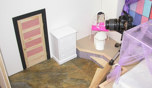
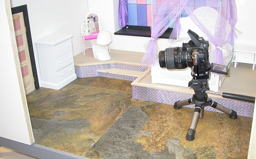
There are always times, well, from time to time…quite often really, when I push the limited size of any set well passed its limits. So to help alleviate this issue with this set, when I want to place the camera well inside the set pointing as much towards the near wall(which isn’t there) as a side wall, I created a simple 12” wide section of blank wall. I drilled the screw holes for attaching it to the ends of the side walls as symmetrically as possible…one 2 ½” from each end and one on center then drilled these holes, through the wall for guidance, into each side wall. This allows me to use it in either corner…or not at all.
You can see below two camera locations and the resulting pictures that would not be possible without the short back wall. This wall can also be used on either the left or right wall of the master bathroom.
|
|
Camera location Camera View
|
|
Camera location Camera View