HOW TO MAKE SERVICE LIFT
- more than an overview but not a detailed step by step tutorial
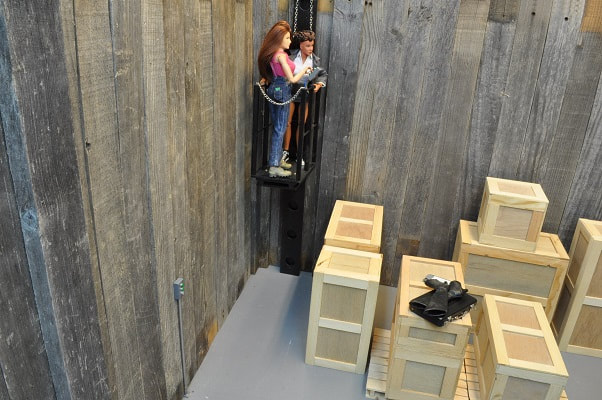
Above is a picture from the story this was made for.
For an episode of “The Great Warehouse Heist”, I required a means for characters to move from the warehouse floor to the roof. Stairs take up a LOT of room and it seems tall ladders are frowned upon so I opted for a two person maintenance/service lift.
PARTS LIST
1 - 1” x ¾” x 28” pine ( MAIN TRACK SUPPORT )
8 - 1” x 1” x ¼” pine ( SPACERS BETWEEN HOLES)
2 - 1” x ½” x ¼” pine ( SPACERS AT ENDS )
2” x 3/16” x 28” LUON ( MAIN TRACK )
1 – 6” x 4” LUON ( CAGE FLOOR )
6 – 5/16” x 5/16” x 7” pine ( CAGE POSTS )
2 - 3 11/16” long 1/8”diameter WOOD DOWEL (CAGE END BARS )
4 - 5 11/16” long 1/8”diameter WOOD DOWEL (CAGE SIDE BARS )
2 - 7 ½” x 3 ¼” LUON ( CAGE TRACK/FLOOR BRACE )
2 – 5/16””sq. x 7 ½” PINE ( CAGE TRACK?FLOOR BRACE SPACERS )
2 – 11/16” x 5/16” x 1 1/8” PINE( Control Boxes )
5 – 3/16” dowels x 3/8” long control box buttons
1 – split dowel, 3/16” dia. x 3/8” long for key hole
3/16 tubing and bender for cage conduit and floor control box
1 – 1 5/8” x ½” x 1/32 brass plate for bottom of floor control box post
3/8” x #2 flathead screw ( CAGE FLOOR )
3/8” x #2 roundhead screws ( CAGE FLOOR )
2 – small eye-screws ( TO ATTACH CHAINS TO CAGE )
A LENGTH OF CHAIN IN EXCESS OF DOUBLE THE HEIGHT OF THE LIFT TRACK
( MY CHAIN IS ABOUT 5 FEET LONG )
4 7/8” OF HEAVY “NECKLACE” CHAIN FOR ACCESS END OF CAGE
THE BEAM or TRACK
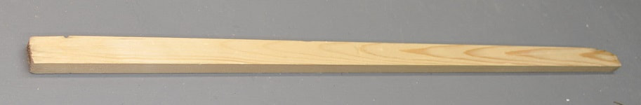
Once I decided on the size and type of cage, covered later, I started on the beam, or track, to carry it. This started as a board cut to the length of my walls, or 28 inches. With a width of 1 inch and a thickness of ¾ inch.
Once I decided on the size and type of cage, covered later, I started on the beam, or track, to carry it. This started as a board cut to the length of my walls, or 28 inches. With a width of 1 inch and a thickness of ¾ inch.
Taking a 2” wide strip of 3/16” LUON 28 inches long, I marked and drilled out nine 1” holes down the length spaced out to 3” center to center with a Forstener bit to give it, what I think is, an industrial look for the actual track for the cage.
It didn’t look right simply placed against the 1” by ¾” piece so I added a series of ¼” thick blocks between each hole to hold it creating a gap between these two parts. It looked much better.
It didn’t look right simply placed against the 1” by ¾” piece so I added a series of ¼” thick blocks between each hole to hold it creating a gap between these two parts. It looked much better.
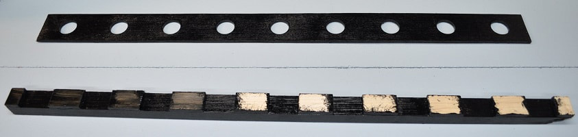
Above are the two parts painted and ready to glue together.
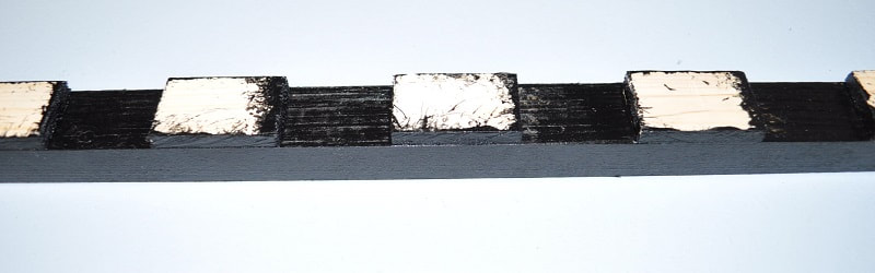
Here’s a close-up of the beam before adding the track.
THE CAGE
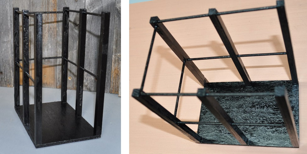
This cage is made with a simple LUON bottom, 3/8” square posts and 3/16” round bars. The 3/16” bars pass through the two center square posts but the holes in the corner posts are blind…or otherwise, they do not go all the way through. This give a much cleaner appearance when done. All of the holes for the dowels were drilled on a drill press set up with a jig on the table so the holes were all the exact same distance from one end and centered to the post. Drilling by eye just would not give as good of a result.
This cage is made with a simple LUON bottom, 3/8” square posts and 3/16” round bars. The 3/16” bars pass through the two center square posts but the holes in the corner posts are blind…or otherwise, they do not go all the way through. This give a much cleaner appearance when done. All of the holes for the dowels were drilled on a drill press set up with a jig on the table so the holes were all the exact same distance from one end and centered to the post. Drilling by eye just would not give as good of a result.
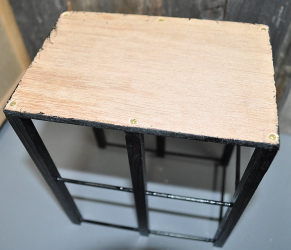
I attached the posts to the floor using 3/8” long #2 flathead screws as shown below.
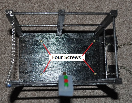
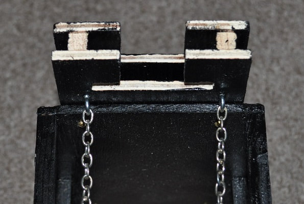
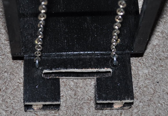
Attaching the cage to the beam is crude but functional…for photos. I simply made TWO LUON panels 7 ½” by 3 ¼” and notched them out as shown to fit over the track. Separating them by two 5/16” square boards as shown, I slid the bottom one towards the beam and clamped it until this sub-assembly rested perpendicular to the track so the cage floor will stay level. I used #2 screws to assemble this in case I needed to make adjustments later. Once this sub=assembly was secure, I cut the front end to a 45 degree to clean up the mismatched ends then screwed it to the cage with the four visible brass screws on the cage floor.
If this were expected to be a high use item, I expect I would have looked into using a drawer guide or something similar for the track. It would have been smooth operating but, for my uses here…this should be fine.
If this were expected to be a high use item, I expect I would have looked into using a drawer guide or something similar for the track. It would have been smooth operating but, for my uses here…this should be fine.
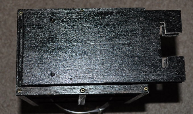
Bottom view with track guides on the right.
|
|
Any unpainted areas are never in view of a camera and many are contact points to the track. I left them unpainted to reduce parts sticking together.
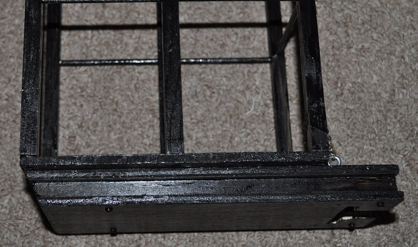
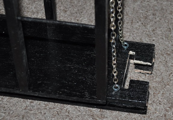
I added two small eye-screws and chain to the cage track/floor brace assembly near the track guides. Had this been more of a major prop, I expect I would have used bicycle chain and made a much smoother working track system. Maybe someday. The chain simply ran up the front of the track and over the wall. And weighted so it stayed semi taut. As the cage is moved up…the weight moves down…out of view.
I added two small eye-screws and chain to the cage track/floor brace assembly near the track guides. Had this been more of a major prop, I expect I would have used bicycle chain and made a much smoother working track system. Maybe someday. The chain simply ran up the front of the track and over the wall. And weighted so it stayed semi taut. As the cage is moved up…the weight moves down…out of view.
|
|
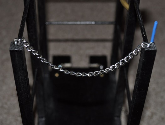
To finish up the cage, I added a chain across the entrance to the cage with a release mechanism made from a paperclip and a piece of shrink tubing for a handle.
CONTROL BOX
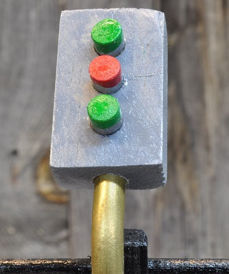
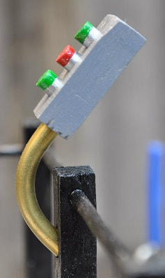
Lastly, I added a control box made from a piece of wood 11/16” x 5/16” x 1 1/8” long, three pieces of 3/16” wood dowel for the buttons and a piece of 3/16 brass tubing I bent with a tubing bender to just short of 90 degrees. I had a couple pieces of 3/16 dowel already painted silver from making Carly’s canopy bed (shown in another tutorial) so I painted the ends green and red, cut them to length of about 3/8” long and shoved them equally into three holes of the painted control box.
Lastly, I added a control box made from a piece of wood 11/16” x 5/16” x 1 1/8” long, three pieces of 3/16” wood dowel for the buttons and a piece of 3/16 brass tubing I bent with a tubing bender to just short of 90 degrees. I had a couple pieces of 3/16 dowel already painted silver from making Carly’s canopy bed (shown in another tutorial) so I painted the ends green and red, cut them to length of about 3/8” long and shoved them equally into three holes of the painted control box.
|
|
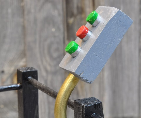
It was tricky to get the hole for the brass tube at the proper angle into the cage post but it came out rather well. I actually established the proper angle in a piece of scrap than clamped this to the post and drilled through both freehand using care NOT to drill completely through the post.
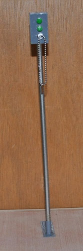
FLOOR CONTROL BOX
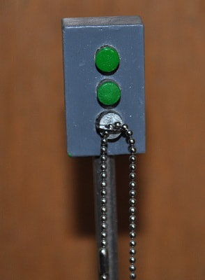
As the above control box is mounted on the cage, I wanted a second control box mounted at floor level to give the appearance that it could be moved upward empty and stored out of the way when not in use. Hence this second box. It is identical to the above box except that the bottom button is replaced by a keyhole. So with “No KEY”…It cannot be operated by unauthorized people. The keyhole amounts to a split wood dowel shoved in the hole so that a “World Peacekeeper’s” Dog Tag, on a chain, may be inserted. This box is mounted to a 3/16” wood dowel which is, in turn, slipped into a base for stability explained next.
As the above control box is mounted on the cage, I wanted a second control box mounted at floor level to give the appearance that it could be moved upward empty and stored out of the way when not in use. Hence this second box. It is identical to the above box except that the bottom button is replaced by a keyhole. So with “No KEY”…It cannot be operated by unauthorized people. The keyhole amounts to a split wood dowel shoved in the hole so that a “World Peacekeeper’s” Dog Tag, on a chain, may be inserted. This box is mounted to a 3/16” wood dowel which is, in turn, slipped into a base for stability explained next.
|
|
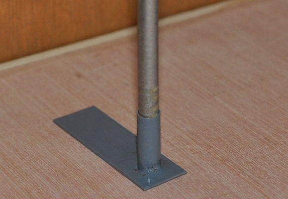
I did not wish to permanently attach this to any wall as the north walls of this room tend to move around for different shots so…I made a simple base for it out of a piece of scrap brass strip 1/32 thick by ½” wide and about 1 5/8” long and a 5/8” long piece of scrap brass tubing with a 3/16 ID.
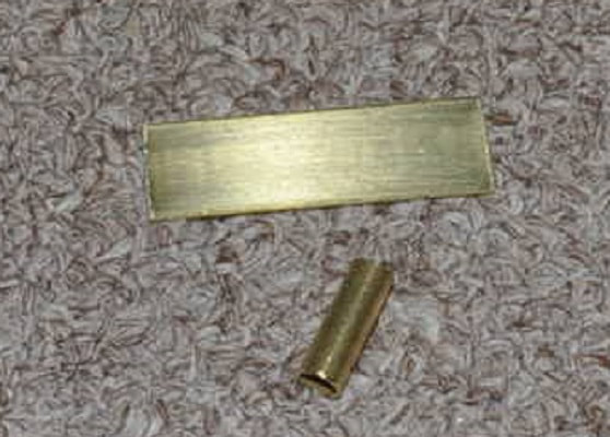
Once soldered together and painted…place the pole for the control box in the tubing and trap the excess of the base under the wall.
|
|
And below we have the finished control box with the key in the lock.