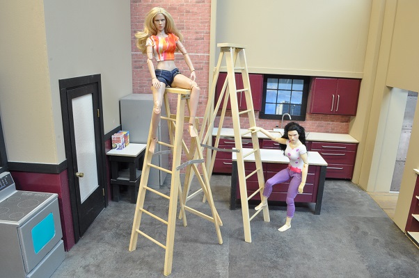
HOW TO MAKE A STEP LADDER
As interesting as building a 1/6th scale extension ladder was…twice…building a step ladder is even more of a challenge as the sides are NOT parallel and the two halves must be properly hinged at the top to function and fold up properly. Here goes.
Take your time. Remember, any time you work in 1/6th scale, ANY error you make is multiplied by 6 in appearance. Some will not matter, or be seen, but some may.
Major Tools I used…
Table saw
Planer(optional) (if you do not have a planer-cut the sides with a new blade as best you can and sand accordingly)
Mill/Drill Press with a good cross-feed table (it is just harder to set up without fine adjustment)
Variable Speed Electric Drill
Metal Lathe (optional)(you can use an electric hand drill or drill press here)
Required materials…
A clean (knot free) length of wood (hard wood is best but I used simple pine)
3/16” dowels (a 14” ladder will require six & a 16” ladder requires seven.) (length / 2 -1)
Four - ¼” metal straps for the folding stops between the halves, .020-.030” thick and a length to be determined later. ( This length is determined by the height of the ladder – A ladder 14” tall will require strips about 1 5/8” long while a ladder 18” tall will require strips about 2 3/8” long. For now wait until that part of the tutorial to cut the length.) (I used an old aluminum license plate @. 025 tk.)
Two #17 wire nails (Must have a typical head – NOT a finishing brad) (the ones I chose are .055” in diameter but could easily be #18 or #19.) to be used as rivets for the folding stops above.
One 3 ¾” x 1.0” piece of .020-.030 aluminum sheet for top metal bracket under the wood top to affix the ladder sections to. Aluminum is best for ease of working with but I ran out and used .020 galvanized steel.
Ten #0 x ¼ RH wood screws (if you cannot find ¼” long screws, buy the 3/8” and grind off the tips if you like) for the folding stops and fastening the top of the back sections to the top bracket.
Three #2 x 1/4” RH wood screws to hold the top board to the aluminum bracket
Wood glue
PRELIMINARY
Determine the length of ladder you want and cut your board to this length. Stay in 2” increments.
My first step ladder is 14 inches long folded up. For this ladder, I went with 18” length sections, making it a 9 foot scale ladder.
The front half is made with the same size material as the extension ladder. About .580” (just under 9/16’) x .280” (just over ¼”) wood.
The back half is made from .280” x .220” wood and the cross braces are made from .140” x .400” wood strips.
The top is 4.000” x 1.000” x .270” thick wood.
The rungs are 3/16” wood dowel material
LET’S START…
With a clean (no knots) piece of wood now cut to length, plane the board(s) to .540 thick (just under 9/16”).
Rip these boards into strips thick enough to be planed to .280 thick x the original .540” wide. I chose about .330 thick to give plenty for cleaning up both sides. Using a planer means NO sanding should be required.
Anytime I do a project like this I will make at least one extra piece in case of accident as it would be a lot of extra work to replace one piece and I often make some shorter pieces of the correct width and thickness for setting up boring the holes and such. In this case I had left over pieces from building another extension ladder so I used them for the front section. But even from these I cut an extra…just in case.
Rip and plane enough wood to make the sides of the back. They are to be .280” x .220 wood the same length as the front two. Again, I suggest making an extra. I would rather throw away an extra piece or two than have to stop to duplicate a damaged part.
I suggest waiting to cut the cross braces as their lengths will be determined best after the front section is complete.
For now cut a board for the top at 4.000” long x 1” wide x .270 thick. For me to plane such a board I need to leave it at least 6.000” long. So if you plan to make more than one ladder…make this piece plenty long and cut the lengths last. Set this piece aside.
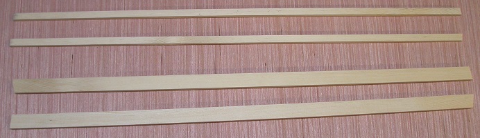
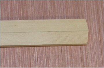
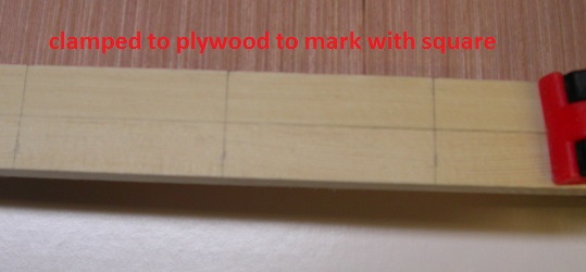
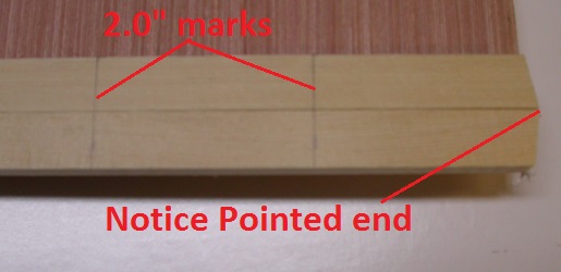
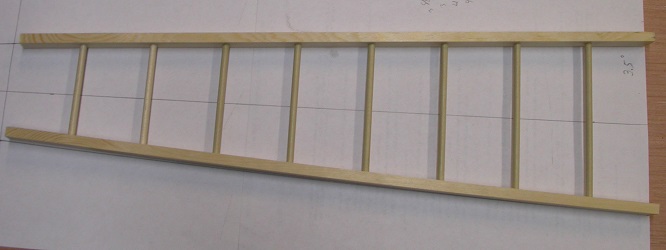
With the front and rear ladder sides cut to the same desired length, sand both ends of the front sides to 10-11 degrees so that the two ends are parallel. (SEE PICTURE) Sand ONE end only of the back section sides to the same angle to be the bottom and set aside. Mark one end of the front sides. These ends will be the bottom and will be referred to as such. Lay the two front side pieces on a table with the bottom ends at the same end and the angles going in opposite directions as shown in picture below. Now mark these two sides, starting at the bottom end, at every 2 inches from one end to the other. The marked sides will be the inner sides of these sides…where the rungs will go.
For now cut a board for the top at 4.000” long x 1” wide x .270 thick. For me to plane such a board I need to leave it at least 6.000” long. So if you plan to make more than one ladder…make this piece plenty long and cut the lengths last. Set this piece aside.
With the front and rear ladder sides cut to the same desired length, sand both ends of the front sides to 10-11 degrees so that the two ends are parallel. (SEE PICTURE) Sand ONE end only of the back section sides to the same angle to be the bottom and set aside. Mark one end of the front sides. These ends will be the bottom and will be referred to as such. Lay the two front side pieces on a table with the bottom ends at the same end and the angles going in opposite directions as shown in picture below. Now mark these two sides, starting at the bottom end, at every 2 inches from one end to the other. The marked sides will be the inner sides of these sides…where the rungs will go.
|
|
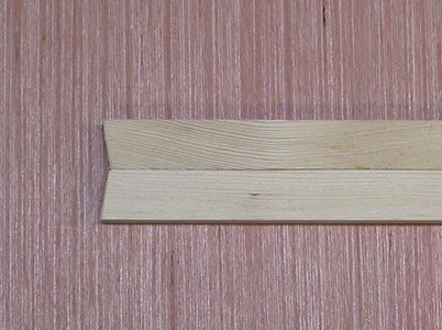
Notice that when properly angled, if one end looks like the left picture, the other end MUST look like the right picture.
|
|
CLAMPED TO A SHEET OF PLYWOOD MARKING FINISHED SHOWING END ALIGNMENT
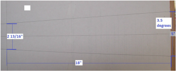
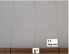
Set up the table on a drill press or, preferably a mill, at 3-4 degrees from level. This angle is determined by the height of the ladder you are building. That being said, it is best to draw up a full scale version of the front section to determine this angle based on having the top ends 2 13/16” apart and the bottom ends 5.000” apart. Simply measure the constructed angle made by the one of the sides to the bottom. (SEE PICTURES) SAVE this sketch for guidance later.
Set up the table on a drill press or, preferably a mill, at 3-4 degrees from level. This angle is determined by the height of the ladder you are building. That being said, it is best to draw up a full scale version of the front section to determine this angle based on having the top ends 2 13/16” apart and the bottom ends 5.000” apart. Simply measure the constructed angle made by the one of the sides to the bottom. (SEE PICTURES) SAVE this sketch for guidance later.
|
|
Place a stop on this table for you to hold the ladder sides against when boring. Because these holes are going into a piece of wood at an angle and NOT straight on, a normal drill bit will not do well. I would recommend using a 3/16” mill bit to bore these holes as a drill bit, unless it is VERY, VERY short, will bend enough and not put the hole where you want it.
Set the bit short so it will not go through the side pieces making a blind hole.
Set the bit short so it will not go through the side pieces making a blind hole.
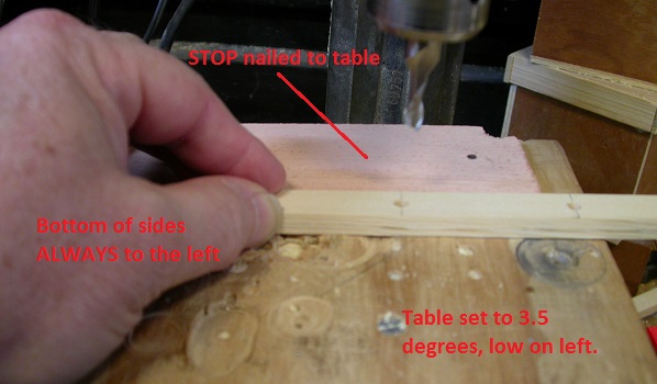
Hold the sides against the stop and bore the holes for the rungs watching so they do not bore through the other side. It is important that the stop is set properly to put the holes in the very middle of the sides as the front edge of one side will be against the stop while the other side will have the back edge against the stop.
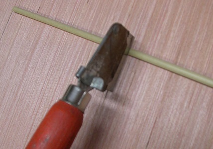
With all the holes in the two front sides bored properly, lay these two sides on the full size sketch you made earlier with the bottom ends obviously at the widest end of the sketch. Place a small section of dowel in a hole on each side to verify the holes were bored at the correct angle. Use a good ruler to “best guess” how long the top and bottom rungs should be. As every rung will be a different length, there is no good reason to do these on a table saw. Though you can. I suggest marking the dowel at the required length and use a single edge razor blade to cut these by squarely pressing the blade against the dowel while rolling the dowel back and forth. (SEE PICTURE)
With all the holes in the two front sides bored properly, lay these two sides on the full size sketch you made earlier with the bottom ends obviously at the widest end of the sketch. Place a small section of dowel in a hole on each side to verify the holes were bored at the correct angle. Use a good ruler to “best guess” how long the top and bottom rungs should be. As every rung will be a different length, there is no good reason to do these on a table saw. Though you can. I suggest marking the dowel at the required length and use a single edge razor blade to cut these by squarely pressing the blade against the dowel while rolling the dowel back and forth. (SEE PICTURE)
I bored the holes to within .060” of penetration. My bottom rung turned out to be 4 5/8” long and the top rung is 2 7/8”.
For a ladder of this height (18”) the rungs would be with the holes bored to .060 short of through.
2 7/8”
3 1/8”
3 3/8”
3 5/8”
3 7/8”
4 1/8”
4 3/8”
4 5/8”
For a ladder of any other height, these values will adjust accordingly based on the top and bottom rungs required for the correct side distance at the top and bottom.
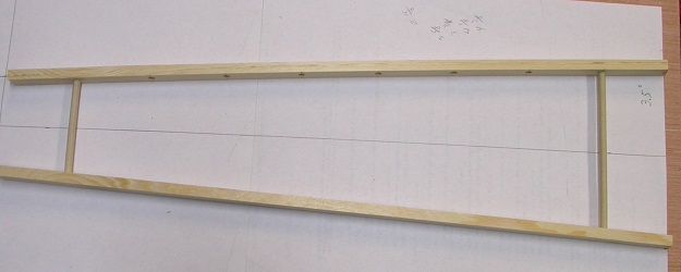
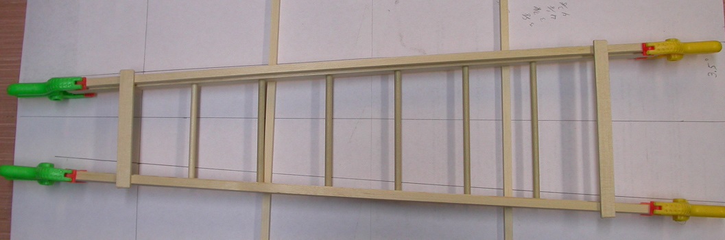
With only the top and bottom rung installed, it should look like this. (SEE PICTURE) And it should match your sketch.
For a ladder of this height (18”) the rungs would be with the holes bored to .060 short of through.
2 7/8”
3 1/8”
3 3/8”
3 5/8”
3 7/8”
4 1/8”
4 3/8”
4 5/8”
For a ladder of any other height, these values will adjust accordingly based on the top and bottom rungs required for the correct side distance at the top and bottom.
With only the top and bottom rung installed, it should look like this. (SEE PICTURE) And it should match your sketch.
Once all the rungs are cut and installed, you have a nearly completed front section. We still need to fabricate and attach the scissor stops for between the two halves and attach this to the top bracket. (SEE PICTURE)
NOW FOR THE BACK SECTION
For now, the nearly finished front section becomes your pattern for the back section.
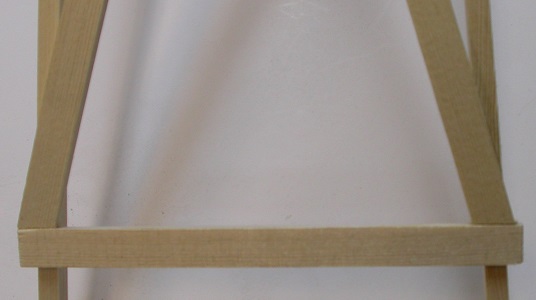
Let’s cut the material for the back braces now. The top and bottom horizontal brace will be installed roughly even with the top and bottom ladder rungs. I like my braces to stick out a little (about 1/8” per side) so they need to be the width of the ladder at these locations plus ¼” for overhang of 1/8” per side. For a VERY rough length for the cross-braces simply place a pencil or similar item across the front section in-line with the top and bottom rungs and guess long on the required length.
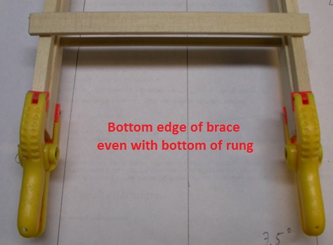
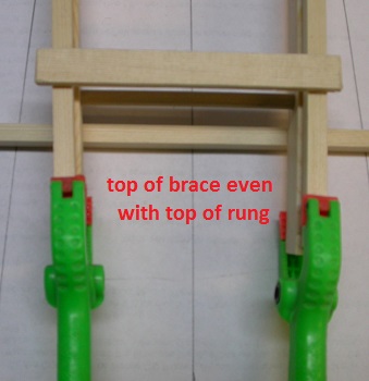
Clamp the rear section sides to the back of the front section as shown so the narrow edge is against the front section and they lay even with the outer sides of the front section. Even up the bottom ends. Lay this flat on a table. I placed wood scraps under it to allow for the clamps. With the horizontal braces cut to length and sanded on the ends, glue them in place. I lined up the bottom of the bottom brace with the bottom of the rung and the top of the top brace lined up with the top of the top rung. My braces worked out to be 5 1/8’ Long and 3 7/16” long. Do not clamp these. Just glue, place them and let them dry. You do not want to add any undue stress on these glue joints to limit any twisting of the assembly once dry and unclamped.
|
|
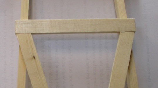
Once this is dry, remove the clamps holding the assembly to the front section. Set the front section aside and lay the rear assembly on a flat surface. It should lay flat. If not add a small weight to and ends that lift up. Hopefully when you glue on the cross braces and the glue dries, this assembly will lay flatter. Carefully cut/sand the ends of the cross braces to fit in place between the horizontal braces. Glue one in place then glue the other one and add weights to the ends until they are firmly seated against the sides. Let dry thoroughly. Set aside.
|
|
BOTTOM OF CROSS-BRACE TOP OF CROSS-BRACE
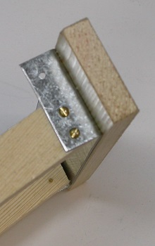
Now the HARD part…the metal top bracket that will hold the top in place while it is screwed securely to the front section and hinged to the rear section.
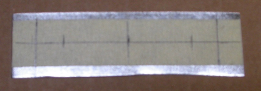
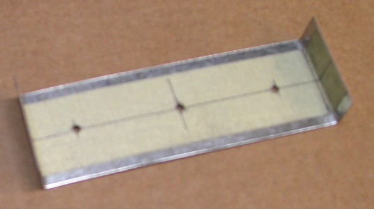
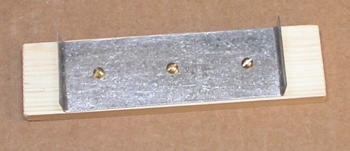
I really like using an old aluminum license plate as it is very easy to cut, bend and drill but I currently just ran out and improvised with a sheet of .020 galvanized steel. Trickier to drill but manageable. Use what you have available in .020-.030 soft metal sheet if you can. Cut a piece to 3 ¾” x 1.0”. Remeasure the top of the front and rear sections. I’d rather cover the metal with masking tape to mark on for clarity and to ensure I have no “mystery” marks on it when I am done. Mark the center-line of this piece across the width and measure out from this point and add two more lines near the ends at the width of the ladder sections. Mark the center-line down the length of the bracket as well. Mark and drill holes for three #2 wood screws at the intersection of the two center-lines and 1” on each side of this center hole As shown below. Use a vice to bend up both ends to 90 degrees as shown.
Now the HARD part…the metal top bracket that will hold the top in place while it is screwed securely to the front section and hinged to the rear section.
I really like using an old aluminum license plate as it is very easy to cut, bend and drill but I currently just ran out and improvised with a sheet of .020 galvanized steel. Trickier to drill but manageable. Use what you have available in .020-.030 soft metal sheet if you can. Cut a piece to 3 ¾” x 1.0”. Remeasure the top of the front and rear sections. I’d rather cover the metal with masking tape to mark on for clarity and to ensure I have no “mystery” marks on it when I am done. Mark the center-line of this piece across the width and measure out from this point and add two more lines near the ends at the width of the ladder sections. Mark the center-line down the length of the bracket as well. Mark and drill holes for three #2 wood screws at the intersection of the two center-lines and 1” on each side of this center hole As shown below. Use a vice to bend up both ends to 90 degrees as shown.
|
|
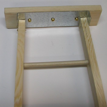
Center the top bracket onto the bottom side of the top board and secure with the three #2 screws using care the screws do NOT break the top surface. Check for fit, particularly over the front section. It does not have to fit perfect as aluminum and the wood will give a bit. The steel I used obviously has less flex.
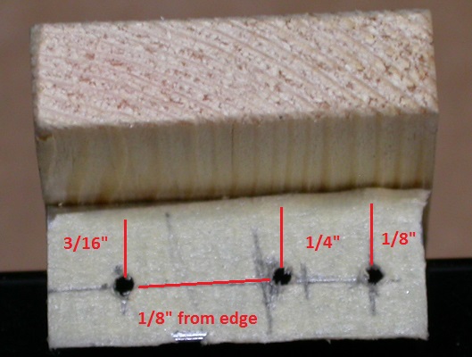
If the fit is acceptable, mark the bracket for the four #0 wood screws to secure it to the front section. If the legs of the top bracket are 3/8” long, drill the two holes on each side at 1/8” from the edge with one 1/8” from the front and the other 1/4” behind it as shown. (SEE PICTURE) Also go ahead and mark and drill two more holes for the back section at 1/8” from the edge and 3/16” from the back of bracket as shown.
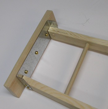
Secure the top bracket to the front section with the four #0 screws. Be sure to drill pilot holes for these screws as they may split the wood being this close to the ends. The top should set in line with the top of the front section so that when the ladder is setup the top will be level with the ground.
|
|
|
ATTACHING THE BACK SECTION
Now the HARDER part yet…normally. Getting the back section properly mounted.
You can experiment using straight pins in these holes to test for location on the back section to ensure the ladder stands well and still folds up properly and squarely to the front section. The location of the holes for the back section should be at 3/16” from the ends and on center. When you are happy with the function, drill the pilot holes and install the two #0 wood screws. I’d suggest drilling ONLY one of the holes…install that screw and then confirm that the other hole is indeed 3/16” from the end. As I mentioned earlier…every error is multiplied by 6 when working in 1/6th scale and if you are off much, it will really show when the ladder is folded up. Once you are sure of the location of the second screw, drill the pilot hole on install this screw.
FABRICATING AND INSTALLING THE SCISSOR LOCKS BETWEEN THE FRONT AND BACK SECTIONS
This scissor lock system should be mounted between the fourth and fifth rungs from the bottom, which should be at a scale height of 4-5 feet. Set up the ladder so the spread on the legs look right. Measuring from outside of the front section to the outside of the back section at the sixth rung from the top should measure near 6”. Now measure from the outside of the front section to the outside of the back section at a location between the fourth and fifth rung from the bottom This distance(A) is roughly what you need the scissor locks to equal when fully open. Cut four strips from the ¼” aluminum stock at least as long as half of dimension A. It can be trimmed later. Drill a hole in one end of each just big enough for the nail to be used as a rivet.
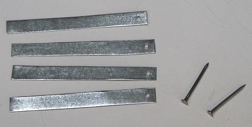
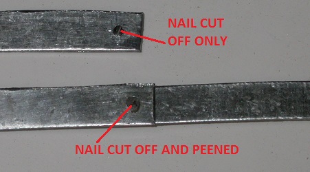
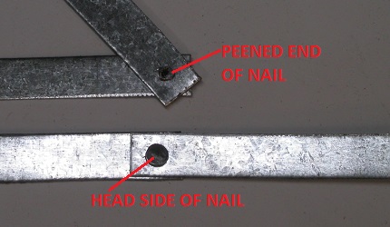
You need to cut off the nails so they are long enough to stick through the two halves of the lock and have no more than 1/16” exposed to peen over. Insert the nail through two sections of a lock. Place the nail head against an anvil. (Most vices have a suitable anvil behind the jaws.) With a small ball peen hammer, lightly start tapping on the exposed, cutoff nail shaft. It should start to mushroom over in short order. Use care not to peen it SO tightly down that the halves do not pivot on the nail freely.
|
|
Now is the time to determine the height you wish to mount the locks and to accurately measure the distance they need to span…screw center to screw center.
For my 18” ladder, measuring between the fourth and fifth rungs from the bottom, with the legs spread to 6” at the sixth rung from the top, is 4 ¼” so I added another ¼” to this to give me an extra 1/8” on the end for drilling the hole. So with my locks are now 4 ¼ “ overall when laid out straight, drill a 1/16” hole in each end for the #0 wood screws at 1/8” from the ends and on center.
After eyeballing the location on the side of the front section of the ladder and making a small mark for the hole, I measured this distance from the mark to the ladder bottom and measured and marked the other side of the front section. With both sides marked, fold the ladder flat and copy these marks to the back section. Drill pilot holes at these marks on the front section on center and attach the locks with the nail head towards the outside.
I would suggest checking the location on the back section on each side before drilling the hole using a straight pin in place of the screw to ensure it folds up properly and each side looks alike. Once you have verified and or adjusted this location, drill the pilot holes in the center of the back side and install the last two screws.
Believe it or not…you are done. If you have any questions, please let me know.