HOW TO MAKE A WELL (Wishing or not.)
|
|
PARTS LIST
32pc – ¾” x 1” x 5 ½” barrel sections
2pc – 16 ½” x 1 3/16” x 3/4” roof support posts
2pc – 5/8” x 5/16” x 11” roof frame (bottom ends)
2pc – 5/8” x 5 16” x 11 3/8” roof frame (sides)
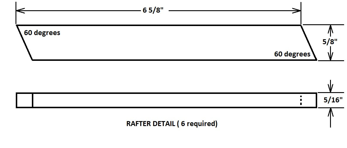
6pc – 5/8” x 5/16” x 7”approx. rafters (ends cut to 30 degrees and parallel)(SEE sketch)
3pc – 3 5/8” x 1” x 3/16-1/4” gussets (at rafter peaks)
¼” dowel rod – 3 pcs bucket crank pivot points and crank handle
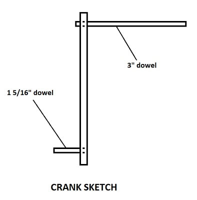
1- 1 5/16” long(handle), 1 – 2” long and
1 – 3” long(handle end)
5/8” dowel rod x 8 7/8” main bucket crank section
3/8” x ¾” x 2 5/8”” crank body
60-80” of 1/8” diameter cord for bucket
Bucket 1/6th scale large bucket
Wood glue
¾ x #18 wire brads
32pc – ¾” x 1” x 5 ½” barrel sections
2pc – 16 ½” x 1 3/16” x 3/4” roof support posts
2pc – 5/8” x 5/16” x 11” roof frame (bottom ends)
2pc – 5/8” x 5 16” x 11 3/8” roof frame (sides)
6pc – 5/8” x 5/16” x 7”approx. rafters (ends cut to 30 degrees and parallel)(SEE sketch)
3pc – 3 5/8” x 1” x 3/16-1/4” gussets (at rafter peaks)
¼” dowel rod – 3 pcs bucket crank pivot points and crank handle
1- 1 5/16” long(handle), 1 – 2” long and
1 – 3” long(handle end)
5/8” dowel rod x 8 7/8” main bucket crank section
3/8” x ¾” x 2 5/8”” crank body
60-80” of 1/8” diameter cord for bucket
Bucket 1/6th scale large bucket
Wood glue
¾ x #18 wire brads
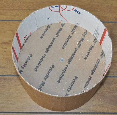
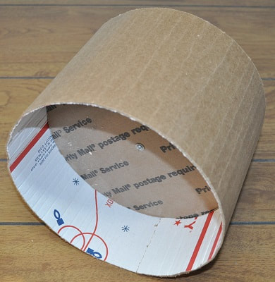
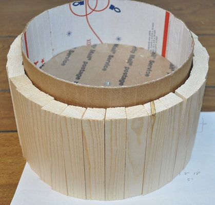
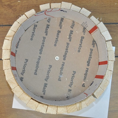
I started with a cardboard mock-up just to try to establish the size as I had no idea. Using a flimsy strip of cardboard 6” wide and just over 28” long, I formed it around two 8 1/5” cardboard circles to keep the structure round. Placing figures next to this, it seemed a bit tall considering I planned to have a top trim around it. So I settled on 5 ½” height for my final pieces for the barrel part.
|
|
I cut 32 pieces of wood from my ¾” thick stock to 5 ½” long and 1” wide…but one side I angled by 10 degrees. Ideally they could be angled on each side 5-6 degrees but a test fit with only one side angled seemed fine. Maybe next time. LOL If you follow the path of only putting an angle on ONE edge…remember to put an angle on BOTH edges for the END piece so it will match up properly with the square edges of the roof support posts. Each end piece MUST have the 10 degree angle or they will NOT match up to the roof supports.
|
|
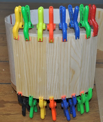
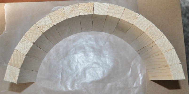
Placing a piece of wax paper around the cardboard form, I started gluing and clamping the boards in place in groups of 8 at a time. This will make ¼ of the barrel part.
|
|
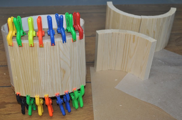
With the four quarter sections dry, I laid out marks on a sheet of cardboard for the outer edge points of a half section, which is 10 ½”, and glued the sections together until I had two half sections.
Now for the posts to hold the roof and bucket crank.
The roof supports are simply 16 1/2” x ¾” (stock thickness) x 1 3/16” wide with the top evenly pointed to 30 degrees to match the roof slope. Drill the ¼” holes now for the location of the bucket crank. This location is 10” from the bottom end and on center widthwise. Due to the snugness of the ¼” dowels I used for the rotation point of the crank, I opened these holes up to 17/64” for easy rotation.
The roof supports are simply 16 1/2” x ¾” (stock thickness) x 1 3/16” wide with the top evenly pointed to 30 degrees to match the roof slope. Drill the ¼” holes now for the location of the bucket crank. This location is 10” from the bottom end and on center widthwise. Due to the snugness of the ¼” dowels I used for the rotation point of the crank, I opened these holes up to 17/64” for easy rotation.
THE ROOF
The roof amounts to a 12” square roof with a 30 degree incline. I made several boards up to be the size of 1/6th scale 2 x 4 or 5/16” x 5/8” for the roof framework and rafters. Note that the bottom framework is NOT 12” x 12”. But rather 12” x 11” in order to fit inside the roof support posts. But the planking will be 12” long so, looking down on it, it will be 12” x 12”. Also note that the pieces that make up the lower edge of the roof should be angled 30 degrees on the top to match the slope of the roof. With the frame glued and held together with “corner clamps”, I drilled pilot holes and drove two ¾” long brads into each corner.
The roof amounts to a 12” square roof with a 30 degree incline. I made several boards up to be the size of 1/6th scale 2 x 4 or 5/16” x 5/8” for the roof framework and rafters. Note that the bottom framework is NOT 12” x 12”. But rather 12” x 11” in order to fit inside the roof support posts. But the planking will be 12” long so, looking down on it, it will be 12” x 12”. Also note that the pieces that make up the lower edge of the roof should be angled 30 degrees on the top to match the slope of the roof. With the frame glued and held together with “corner clamps”, I drilled pilot holes and drove two ¾” long brads into each corner.
If you do not have a set of at least four of these clamps with your woodworking tools I would highly recommend buying a set or two. Most lumber yards carry them and Harbor Freight Tools carries a budget version that work great too.
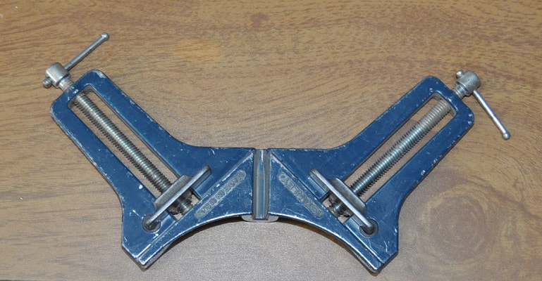
Corner/Frame Clamp
Cut 6 identical rafters as shown in the sketch below. For the assembly, I clamped them in place to the roof frame to get the alignment correct then glued the gussets in place to one side. You can put one of each side of the center one if you like but I did not. This step will be continued after the ROOF SUPPORTS.
ROOF SUPPORT POSTS
These posts ARE a part of the bottom barrel section but are 16 ½” long from their bottom to the tip of the point at the top. I notched out the top as shown to accept the rafters being inside the main roof frame.
These posts ARE a part of the bottom barrel section but are 16 ½” long from their bottom to the tip of the point at the top. I notched out the top as shown to accept the rafters being inside the main roof frame.
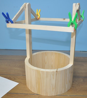
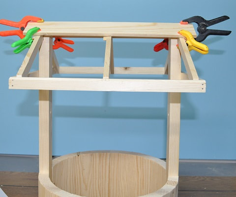
What you see below is what I am going for. Very little is glued together at this point as I am still checking fit of the roof supports.
|
|
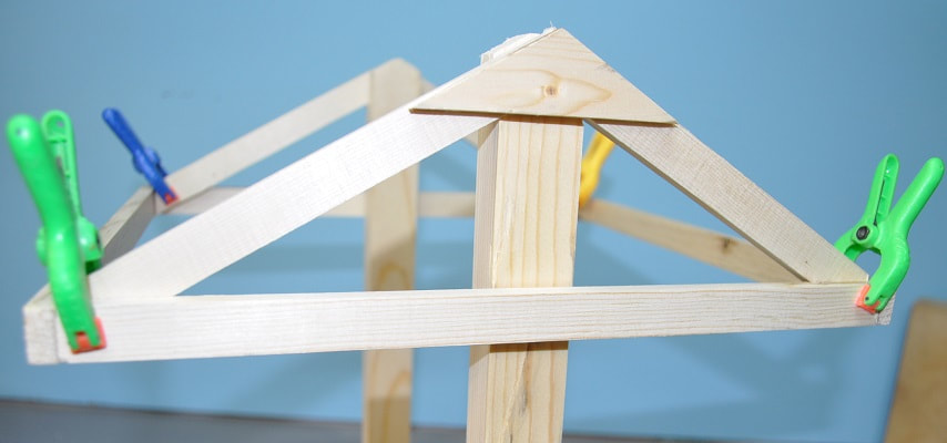
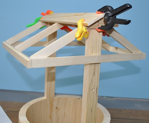
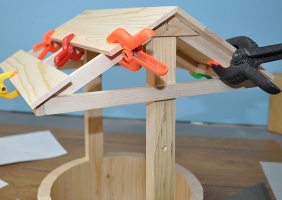
Below is a close-up of the roof frame and two of the three gables clamped in place.
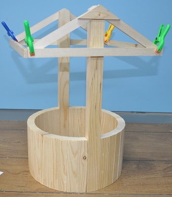
I was impressed that the two barrel haves and the roof supports fit remarkably well so I was able to glue up the sides of the roof supports, get everything positioned and clamp it all together with a length of twine, using a scrap of wood as a tourniquet to apply pressure around the circumference.
If you notch your roof supports as I did, make sure they are to the outside during assembly.
At this point, the roof frame can be finished and installed. If you did not angle the tops of the roof frame at the bottom of the slope, be sure to account for this by gluing the rafters in place HIGH so your roof planks still lay flat.
At this point, the roof frame can be finished and installed. If you did not angle the tops of the roof frame at the bottom of the slope, be sure to account for this by gluing the rafters in place HIGH so your roof planks still lay flat.
|
|
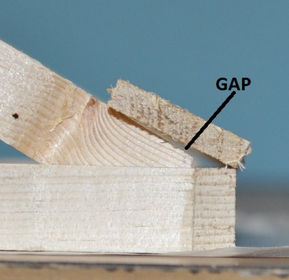
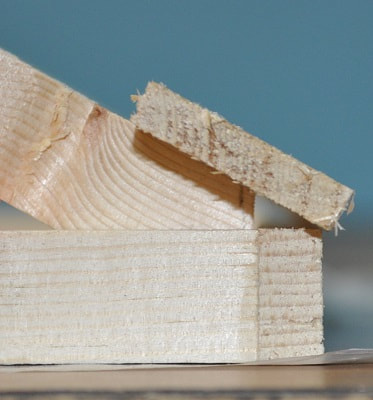
(Figure 1) (Figure 2)
Unacceptable fit Acceptable fit
Unacceptable fit Acceptable fit
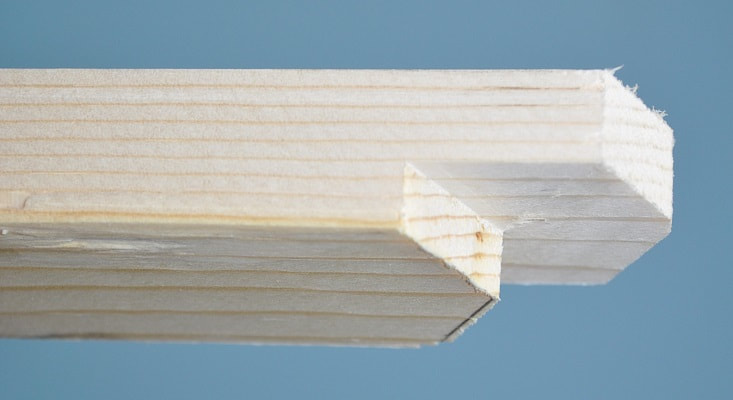
Notice the gap under the plank and the size of the triangular void at the end of the rafter in Figure 1 because the roof frame is NOT angles 30 degrees and the rafter is set too low.
Notice, by raising the rafter until the top surface is in the same line as the outer edge of the roof frame, that the gap under the plank is gone but the triangular void IS bigger. SEE figure 2
Notice, by raising the rafter until the top surface is in the same line as the outer edge of the roof frame, that the gap under the plank is gone but the triangular void IS bigger. SEE figure 2
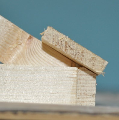
Figure 3
Best Fit
Best Fit
Also notice I did not choose to bevel the entire top edge of the roof frame so there is still a very small triangular void at the end of the rafter but, by doing it this way, the rafter did not stick out the bottom which it would if I’d removed more material from the frame.
Now to glue the rafters in place. The end two are simple enough. Just make sure the gussets are to the outside during assembly and simply center the third pair of rafters between them.
Now to glue the rafters in place. The end two are simple enough. Just make sure the gussets are to the outside during assembly and simply center the third pair of rafters between them.
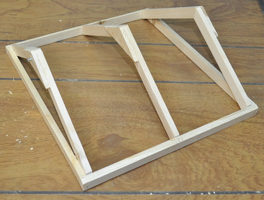
ROOF FRAME WITH RAFTERS GLUED IN PLACE
Affixing this assembly to the roof supports can be a simple matter of glue and clamps or…I chose to use screws for now to see if there was any merit in being able to remove the roof in order to shoot down into the well easily. So I counterbored the hole for a #4 flat head screw at the very peak as you can see in the above picture. I may add another below it on each side into the roof frame but for now…the one will do. The screws would also offer some ease of future repairs as well. The plan is also to finish this whole item with clear, satin latex wood finish. So having the ability to break it down into two subassemblies…applying the finish will be easier as well.
The width of the planks used on the roof is up to you. To cover the 7 inches of each side I would suggest 1 3/16”, 1 7/32” or 1 ¾” which will require 6, 5 or 4 planks preside, respectively. I went with the 1 ¾” width by about 3/16” thick. Be sure to bevel the two at the peak to 30 degrees in order to have a clean match. Even though I planned to add two more trim boards at the peak, that would be 1/2 “-5/8” wide, I found the fit at the peak was so good I didn’t bother.
I glued and clamped the two beveled “peak” boards in place first ensuring that they stuck over each end equally then worked my way down.
|
|
|
BUCKET CRANK
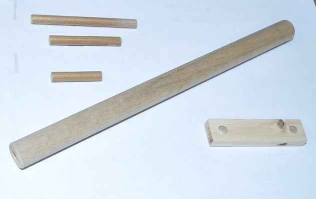
Bucket Crank Parts
I took an 8 7/8” length of 5/8” wood dowel and drilled a ¼” hole over an inch deep into both ends for the main beam of the crank mechanism. Slipping a length of ¼” dowel through the roof support posts and into these holes will support it.
THE CRANK BODY
Drill a ¼” hole on center and 3/8” from each end of the 2 5/8” long crank body. One for the handle and one for the pivot pin of the assembly.
Drill a ¼” hole on center and 3/8” from each end of the 2 5/8” long crank body. One for the handle and one for the pivot pin of the assembly.
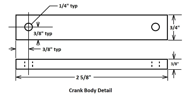
Press the 1 5/16” length of dowel into one of the holes in the crank body until it is flush with the other side. Glue if fit is loose…but mine fit VERY snug.
Press one end of the 3” dowel into the other hole as shown so it sticks through to the handle side by about 1/8” for cosmetic sake.
Press one end of the 3” dowel into the other hole as shown so it sticks through to the handle side by about 1/8” for cosmetic sake.
Holding the 5/8” diameter dowel between the roof supports, insert the 2” and 3” dowels through the roof supports and into the ends of the 5/8” dowel.
Insert the handle assembly until there is a 5/8”-3/4” gap between the handle body and the roof support.
Insert the other dowel until it sticks out of the other roof support by ¼” approximately. This is another cosmetic distance. Adjust it to suit yourself if you like just do not push it in flush or you may never get it out.
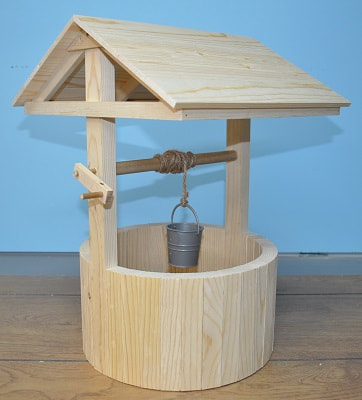
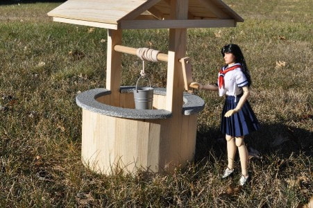
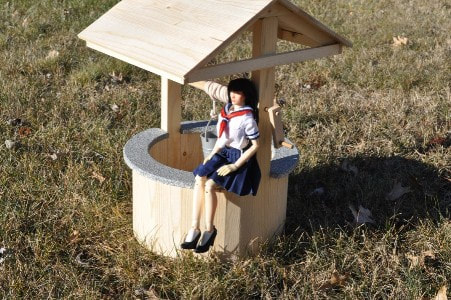
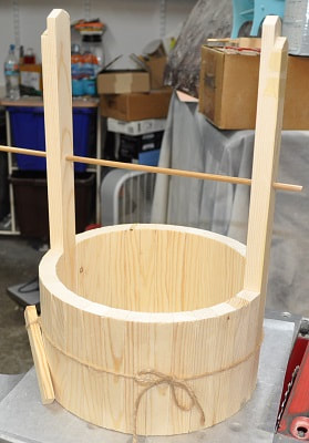
Here it is with the roof complete, the crank installed and a temporary rope holding a bucket. All that is left is some trim pieces around the top of the barrel section.
WELL TOP LEDGE
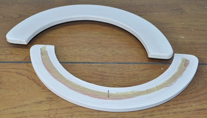
To fashion the top ledge I had in mind, I took some scraps of LUON (3/16” thick, cheap plywood used often as underlayment) and cut four arcs as shown in the sketch. Gluing them together as pairs, I had pieces now 3/8” thick. I could have used 3/8 plywood, if I had any but the grain on the LOUN is much finer and will require much less effort to smooth up so I can paint it.
To fashion the top ledge I had in mind, I took some scraps of LUON (3/16” thick, cheap plywood used often as underlayment) and cut four arcs as shown in the sketch. Gluing them together as pairs, I had pieces now 3/8” thick. I could have used 3/8 plywood, if I had any but the grain on the LOUN is much finer and will require much less effort to smooth up so I can paint it.
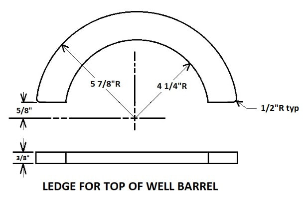
These radii will give a ledge that will overhang on the inside by 5/16” and the outside by 9/16”. This will be heavily primed, to hide the fact that it is wood, then spray painted to resemble stone as I did the edge of the pond I made in another tutorial. The ½” radius on the two outside corners is not necessary but I felt it softened the appearance as opposed to the abrupt flat ends.
The outside radius is easy enough to sand properly with and bench mounted disc sander. If you do not have access to a good LARGE drum sander, the inside radius will be a lot more work to get smooth. I used a 4” diameter drum on mine and it went very well.
I used care when priming and painting these to protect an area on the bottom of each so I would not be gluing to a painted surface. While applying the clear finish to the rest of the well, I did not apply any to the top of the barrel for the same reason.
Before priming, I drove three ¾” brads into the bottom of each section so I could prime the bottom then stand them up on these brads so I could immediately prime the edges and top. I left these brads in for the spraying of the final finish.
After applying a good coat of KILZ primer and sanding any rough spots, I used Rust-oleum brand, American Accent STONE spray paint in the textured grey color, as I did on my pond boarder.
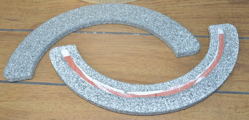
Here are the ledges, one upside down to show the exposed wood for gluing.
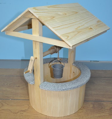
This is what I was going for. I only hope to find a better rope. Look for this wishing well in upcoming stories.