HOW TO MAKE A WOODEN FOOT BRIDGE

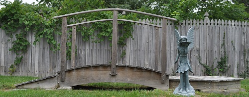
Years ago I came across plans online for making a foot bridge…and built one for our backyard as an oddity and something for the kids and grandkids to play on.
(Pictured below)
(Pictured below)
Now I have repurposed the plans for a 12 foot long foot bridge for the 1/6th world.
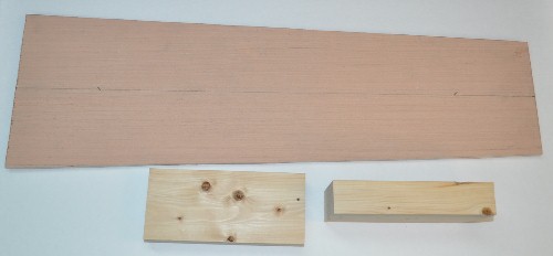
The construction is very straightforward but I will cover in detail what I did for the actual bridge section. I first took some nice ¾” pine boards and cut them down to various widths that I could saw in half thickness wise. Most were 24” long as that was the longest I would need for the sides of the bridge and the transition ramps. I also cut another 3/4" thick board to 26” long for the footer ramps (to be painted to look like cement). These will NOT be cut in half so you need four total, plus enough scraps for the four ends.
With the required lumber sawn in half, I ran everything for the bridge sides and cross braces through my planer to a final thickness of .300” or about 5/16ths”. The two bridge sides are just over 2 5/8” wide. I also ran the footer parts through the planer to 1/2" thick.
NOTE: It seems most any time I try to cut a corner on a project it comes around to bite me. This bridge was no exception. I was thinking I could save some time and effort by leaving the bottom FLAT. Yes, it saved some time and made gluing in the cross pieces easier…but it just looked wrong to me so I added the curvature to the bottom WAY late in this project. This will be noted in my text.
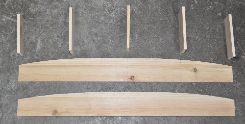
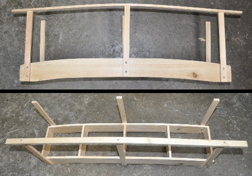
Below you will see the two sides, with the FLAT bottom and the five cross pieces. You may find it easier to use 6 cross braces, having the middle two about 2” apart to make attaching the center rail posts easier. Judge for yourself. But this is when the curvature to the bottom should be applied…not later. The cross pieces are from the .300” thick material and are 4 ¾” long. The height of each piece is dependent on the location they are assigned. The ends should completely close off the ends while the others do NOT want to show below the bottom of the bridge or stick out above it. Being 1/8” short is better than sticking below or above any at all.
My wife and I laid out the top radius with a pencil and a length of string on our kitchen floor…it IS a large arc. The arc should connect three points which include the center point of one side and two points 7/8" down from the tops of the ends. The inner arc should leave an approximate 2.00” flat at both ends of the other side as shown five pictures down.
The construction is very straightforward but I will cover in detail what I did for the actual bridge section. I first took some nice ¾” pine boards and cut them down to various widths that I could saw in half thickness wise. Most were 24” long as that was the longest I would need for the sides of the bridge and the transition ramps. I also cut another 3/4" thick board to 26” long for the footer ramps (to be painted to look like cement). These will NOT be cut in half so you need four total, plus enough scraps for the four ends.
With the required lumber sawn in half, I ran everything for the bridge sides and cross braces through my planer to a final thickness of .300” or about 5/16ths”. The two bridge sides are just over 2 5/8” wide. I also ran the footer parts through the planer to 1/2" thick.
NOTE: It seems most any time I try to cut a corner on a project it comes around to bite me. This bridge was no exception. I was thinking I could save some time and effort by leaving the bottom FLAT. Yes, it saved some time and made gluing in the cross pieces easier…but it just looked wrong to me so I added the curvature to the bottom WAY late in this project. This will be noted in my text.
Below you will see the two sides, with the FLAT bottom and the five cross pieces. You may find it easier to use 6 cross braces, having the middle two about 2” apart to make attaching the center rail posts easier. Judge for yourself. But this is when the curvature to the bottom should be applied…not later. The cross pieces are from the .300” thick material and are 4 ¾” long. The height of each piece is dependent on the location they are assigned. The ends should completely close off the ends while the others do NOT want to show below the bottom of the bridge or stick out above it. Being 1/8” short is better than sticking below or above any at all.
My wife and I laid out the top radius with a pencil and a length of string on our kitchen floor…it IS a large arc. The arc should connect three points which include the center point of one side and two points 7/8" down from the tops of the ends. The inner arc should leave an approximate 2.00” flat at both ends of the other side as shown five pictures down.
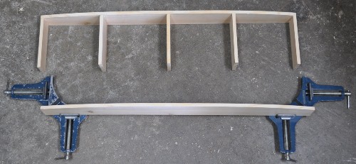
The clamps shown below are great for gluing boards at 90 degrees to each other.
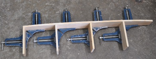
With all the cross pieces glued and nailed to one side, it is a simple matter to attach the other side.
Here is the completed Main Sub Assembly before removing the area on the bottom edge.
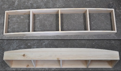
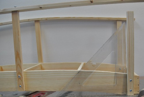
You can see below the area I cut away with a saber saw. I ended up cutting the last of the cross pieces with a hacksaw. Not a lot of fun but it got the job done.
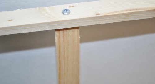
The railing posts are .300” thick x 5/8” wide and 8.0” long. They will stick above the bridge sides 6.0” before applying the planking. I inset the end posts 5/8” from the ends of the bridge. The other post obviously goes on center. The bolts to hold the posts to the bridge are 4-40 nuts and bolts. ¾” long bolts should do but my store was out so I bought longer ones that I will either cut off, replace or simply leave ASIS since they will not be seen. Holes are drilled ½” and 1 ½” from one end of the posts. Since I did put a cross piece on the same centerline of the bridge, I used #4 x 1” pan head screws for this installation. You have to be very careful drilling your pilot holes as the cross piece is only .300” thick. You do not want to drill through a side of this cross piece. The tops of the end posts should be angled to match the bottom of the rail by about 1/16” to nothing. Be very careful that they are angled the correct direction. NOTE: Adding this angle is easier AFTER the rail has been completely installed but can be done now. Just be aware it MAY effect the drilling of the rail mounting holes causing the drill to wander downhill on the angle.
When attaching a railing, drill the hole for the center post screw first. Drill the pilot hole in the post and secure the rail to it.
Wood is very forgiving and these posts should be able to be adjusted to relatively square to a flat surface by simply pushing and snugging the screws.
Locate the center of the end posts on each railing and drill the through hole for the screw. Find and mark the location of these through holes on the tops of each post and drill a pilot hole for the screw. Install all six railing screws. Now is the best time to add the angle to the end post’s tops. Remove the railing end screws and, one by one, remove and add the angle to the tops of each post and secure them back to the bridge. Reinstall the railing screws.
ADDING THE PLANKING
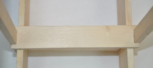
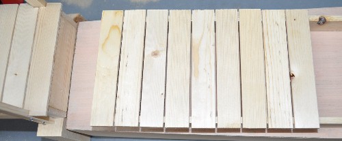
The planking is made from 1 1/16” wide x 5 7/8” long x 3/16 (.200”) thick wood pieces. Notch and glue a piece to both ends as shown below. I had mine hang over the end a bit as this is to hang over the wooden transition ramp to be built in a moment.
The planking is made from 1 1/16” wide x 5 7/8” long x 3/16 (.200”) thick wood pieces. Notch and glue a piece to both ends as shown below. I had mine hang over the end a bit as this is to hang over the wooden transition ramp to be built in a moment.
Notch and glue the plank that goes in the center.
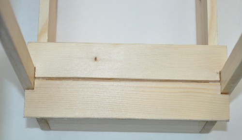
Notch a second plank for each end so there is about 1/16” gap between the two end planks. DO NOT GLUE YET. Fill in the remainder by placing (not gluing) planks over the rest of the bridge. Experiment a bit to get a feel for the required gap between the planks for them to be spaced evenly. Glue in all remaining planks, adjusting the gaps as you go to keep them evenly spaced.
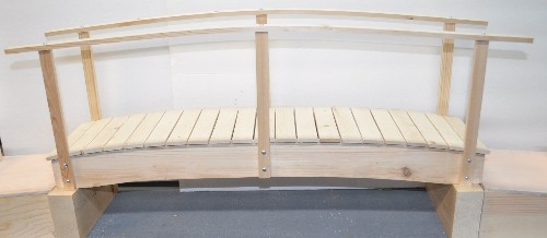
Below is the finished bridge section. The end posts look angled out but that is simply the perspective of the shot. They are reasonably square.
FABRICATING THE RAMPS
FABRICATING THE FOOTERS
I believe that most people will have their own ideas for the transition they would prefer from the bridge to the ground so I am not going into nearly as much detail on these two sections as I did on the bridge itself. But this should promote some ideas and give some guidance nevertheless.
Here are two sketches of what I aimed for on each end of my bridge. The first is the bridge footer and transition ramp while the second is of the wood transition ramp.
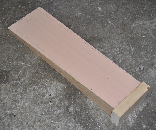
This first one will be painted up to look like cement after adding the 3 3/16” x 7 1/16 x 1 7/16 wood block to the 6” end.
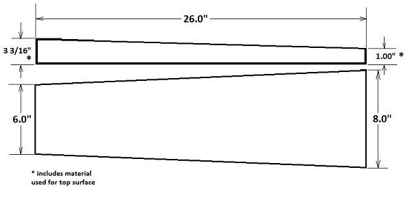
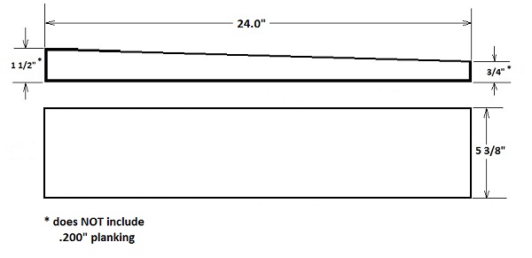
These height dimensions will need adjusted if your planking is different than the .200” thick wood I used.
THE BASIC CONSTRUCTION
The “cement looking” footers below consist of two pieces of Luon 26” long, 8” wide at one end and 6 1/8” wide at the other for the tops of the transition footer and two pieces of wood 3 3/16” x 7 1/16 x 1 7/16 for the main supporter of the bridge ends. These two structures will look like cement when we are done.
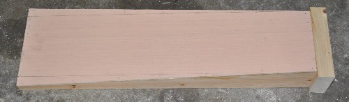
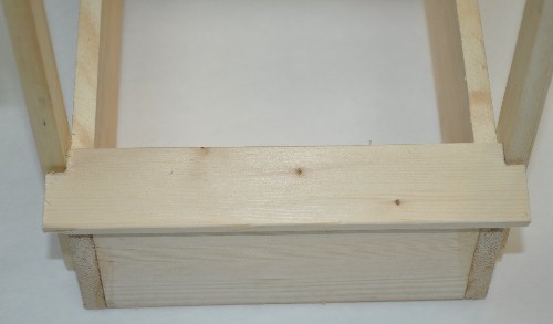
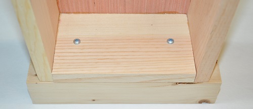
You will also need a supply of ½” thick wood for the sides and ends of the ramps. I used two #6 x 1” wood screws to fasten the wood block to the end as shown below.
|
|
Two screws holding wood block to ramp Ready for priming and painting.
When painting, I suggest using a roller to apply a good primer to these footer transition ramps and the blocks as separate units to get the better finish and hide the fact that these ARE actually wood as a roller gives a bumpier surface than a brush. Then screw the pieces back together and apply the “cement grey” color to each footer as a complete assembly. The ends of the block and around the top edge of the sides may take two or three coats to hide the wood grain sufficiently.
THE WOOD TRANSITION RAMPS
When I cut the sides for the bridge, I cut four extra pieces for the wood sections of the transition ramps at each end of the bridge. Again, 24” long.
The “WOOD” part to these transition plates is made much as the bridge was. Same length. Same width. But wedge shaped rather the crowned. I placed two cross braces in my 24” length at 8” from each end. Watch that these do not stick up above or below the sides. My thinking, in making the cement footer part 2” longer, was that the cement footer would make one step 6” high (in 1/6th scale) and 12" wide and then the wood transition ramp would make another 6” step up, also 12" wide…then you have the ramp to the bridge.
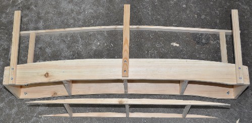
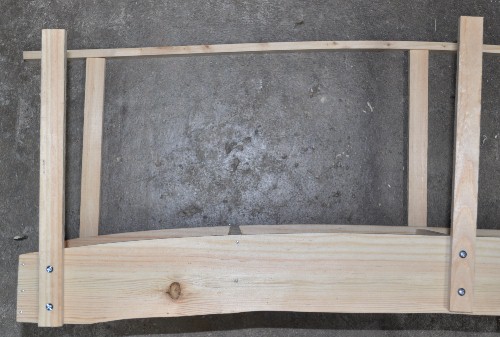
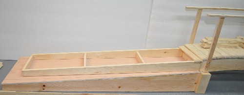
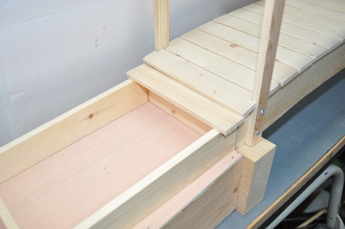
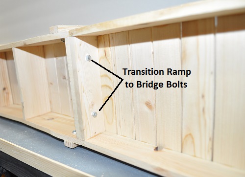
You can see below how these all fit together. I used another two #4-40 x ¾” long bolts and nuts to fasten these transition ramps to the bridge. This is probably not necessary but I want it to not shift and not be noticed while I am using it. The first plank is attached to the very end of the tallest end of this section. With an approximate 1/16” between each plank, it takes 21 planks on each ramp. These planks are glued in place with NO clamps. Simply glued, adjusted as needed and left to dry. On any project where you use clamps to hold wood in place, especially thinner wood, you run the risk of having the project twist when the clamps are removed. Once the first planks were applied and dried on each section, I only added two at a time to limit the chance of something shifting and not being caught.
THE WOOD TRANSITION RAMPS
When I cut the sides for the bridge, I cut four extra pieces for the wood sections of the transition ramps at each end of the bridge. Again, 24” long.
The “WOOD” part to these transition plates is made much as the bridge was. Same length. Same width. But wedge shaped rather the crowned. I placed two cross braces in my 24” length at 8” from each end. Watch that these do not stick up above or below the sides. My thinking, in making the cement footer part 2” longer, was that the cement footer would make one step 6” high (in 1/6th scale) and 12" wide and then the wood transition ramp would make another 6” step up, also 12" wide…then you have the ramp to the bridge.
You can see below how these all fit together. I used another two #4-40 x ¾” long bolts and nuts to fasten these transition ramps to the bridge. This is probably not necessary but I want it to not shift and not be noticed while I am using it. The first plank is attached to the very end of the tallest end of this section. With an approximate 1/16” between each plank, it takes 21 planks on each ramp. These planks are glued in place with NO clamps. Simply glued, adjusted as needed and left to dry. On any project where you use clamps to hold wood in place, especially thinner wood, you run the risk of having the project twist when the clamps are removed. Once the first planks were applied and dried on each section, I only added two at a time to limit the chance of something shifting and not being caught.
|
|
|
|
At least every 6-8 planks, check that they are still running perpendicular to the side with a combination-square or similar device. You can also measure from the unfinished end to the edge of the last plank. You do not want to get to the other end to find the last plank is 1/8” or more out of square. One of my ramps went together perfectly end to end while the other was off by just under 1/16” after 9 planks. To correct this, I added three layers of masking tape to the end of the 6” ruler I was using as a spacer as I glued on the planks to make that end thicker. This made a .010” correction on every subsequent plank until the needed correction was achieved which took about 5 planks.
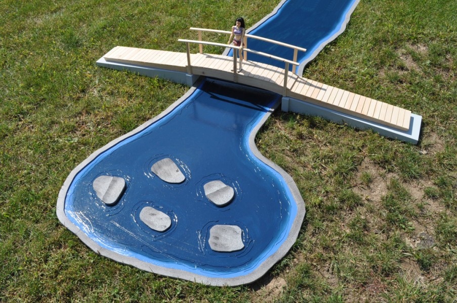
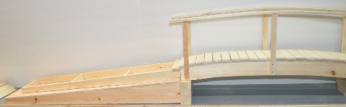
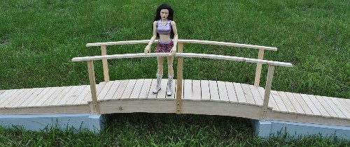
Now you can see the end result with the footer transition ramps primed and painted a cement grey making a rather nice 1/6th scale wooden foot bridge. If this proves as useful as I hope it will, I expect to build a few different footers and transition ramps to make it even more useful.
Now you can see the end result with the footer transition ramps primed and painted a cement grey making a rather nice 1/6th scale wooden foot bridge. If this proves as useful as I hope it will, I expect to build a few different footers and transition ramps to make it even more useful.
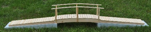
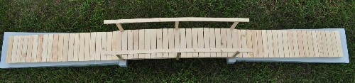
Add a simple pond effect and you have this...