HOW TO MAKE A POP MACHINE ( OPENING TYPE )
|
|
|
|
PARTS LIST
MAIN CABINET
6 ¼” x 4 ¾” Luon top
5 7/8” x 5 ¾” Luon bottom
11 13/16” x 4 ¾” Luon sides (2)
3 7/8” x 5/16” x 5/16” pine corner braces (4)
11 11/16” x 5 11/16” Luon back
11 9/16” x 5 7/8” Luon internal front panel (optional)
9/16” x 1/8” x 11 ¾” hinge cover plate(door)
9/16” x 1/8” x 12” hinge cover plate(cabinet)
¾” x 1” HINGE (3)
¼” (approx.) round, rare earth magnets (2) door latch(optional)
Block to hold one magnet explained under DOOR LATCH below(optional)
FRONT DOOR SECTION
11 3/8” x 5 7/8” Luon front
11” x 5 7/16” Luon back
1 3/16” x 3/16” x 5 7/8” outer frame-top/bottom(1 each)
1 3/16” x 3/16” x 11 ¾” outer frame-sides(2)
1 ” x 3/16” x 5 ½” inner top/bottom(1 each)
1 ” x 3/16” x 11 3/8” inner sides(2)
3/8” x 3/8” x 11/16” wood stock corner braces(4)(2 optional for center point on each side)
1/16” x 1/8” x 11 3/8” pine or basswood to hold left side of graphic
1” x 1/8” x 11 3/8” Selection Panel
¼”-3/8”” x 1/8” x 4 11/16” (2) to hold top& bottom edges of top graphic
¼”-3/8”” x 1/8” x 4 11/16” (1) to hold bottom edge of bottom graphic, if used
POP CHUTE
1/16” thick hobby plywood(or basswood) pop chute
5/32” x 5/32” wood pop chute bezel (SEE sketch below)
¼” x 1/16” wood pop chute rear trim
INCIDENTALS
Glue
#2 x 3/8” Flat Head wood screws
Screws for the magnetic latch(optional)
MAIN CABINET
As making this unit open properly will be the biggest challenge on this project, great care must be observed in placement of the corner braces. If you have to, tape the four sides together with masking tape and mark all the back corners where these panels meet. You do not want to glue a corner brace in the wrong orientation making two left or two right sides.
To the inner top sides glue a corner brace so it is 5/16” from the back edge. To one end of each side panel glue a brace so they are 5/16” from the back edge. With a 3/16” thick back panel, that would make it recessed by 1/8” when assembled and leave enough space at the front for the door to close with or without the 3/16” inner panel which is optional.
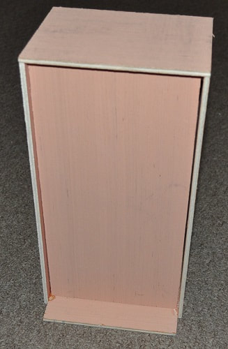
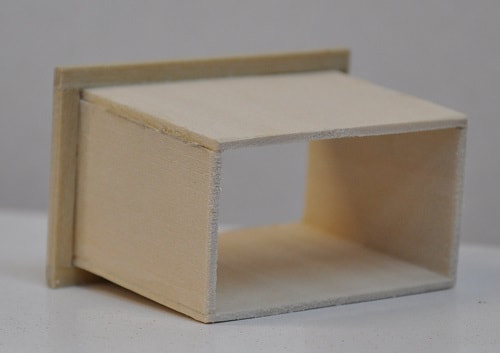
When the braces are dry, finish the assembly of the cabinet walls. You should end up with this, pictures below, and it should be rather sturdy.
As making this unit open properly will be the biggest challenge on this project, great care must be observed in placement of the corner braces. If you have to, tape the four sides together with masking tape and mark all the back corners where these panels meet. You do not want to glue a corner brace in the wrong orientation making two left or two right sides.
To the inner top sides glue a corner brace so it is 5/16” from the back edge. To one end of each side panel glue a brace so they are 5/16” from the back edge. With a 3/16” thick back panel, that would make it recessed by 1/8” when assembled and leave enough space at the front for the door to close with or without the 3/16” inner panel which is optional.
When the braces are dry, finish the assembly of the cabinet walls. You should end up with this, pictures below, and it should be rather sturdy.
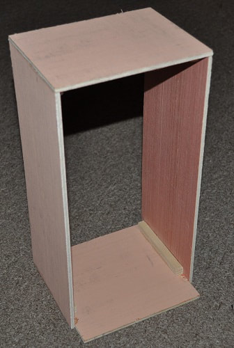
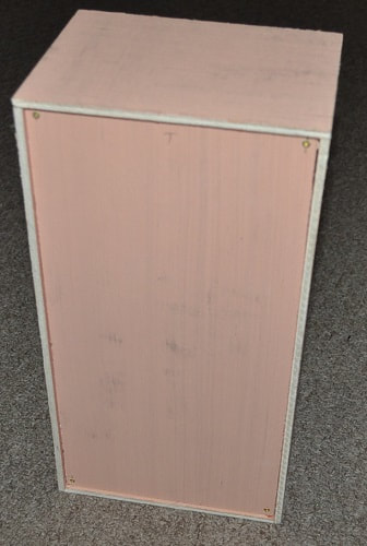
Mark the front and back cabinet panels in each corner for the screws to secure the panels to the corner braces. Drill a #50(.070”) hole (a 1/16” hole will do if you do not have a number drill bit set. Just use care as this will be nearly .010” smaller hole) for each screw and countersink the hole to the proper depth for a #2 screw. Insert the front and back cabinet panels into the cabinet frame and continue the pilot holes into the corner braces to prevent splitting the wood. Install the eight #2 x 3/8 flat head wood screws.
NOTE: I made the front panel a bit small as I wanted to be able to easily remove it and reinstall it from time to time for a special photo shoot but if you never intend to remove it…the closer the fit…the better.
NOTE: I made the front panel a bit small as I wanted to be able to easily remove it and reinstall it from time to time for a special photo shoot but if you never intend to remove it…the closer the fit…the better.
|
|
Cabinet Front Cabinet Back
OPENING DOOR PANEL
Again, I would suggest getting the Pop Chute completed early as it will be needed very soon. Jump down to Pop Chute below to start this sub-assembly. I do not go into great detail in this assembly as it should be a simple cut and glue sub-project. See the sketch under POP CHUTE below.
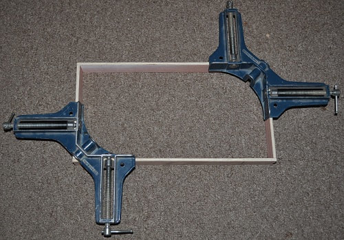
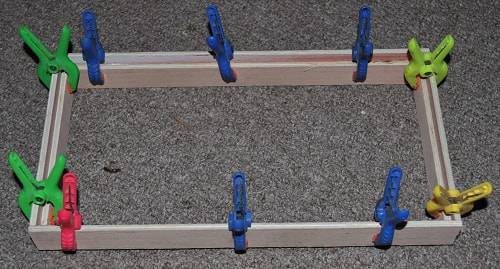
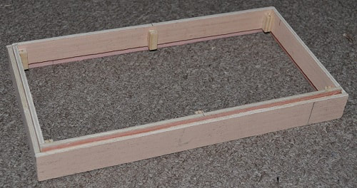
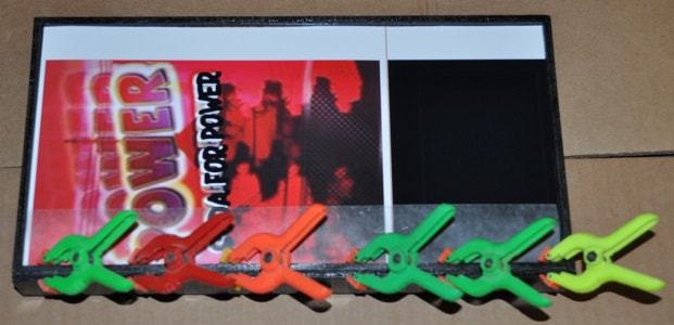
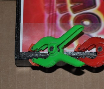
Glue the sides to the top and bottom with the top and bottom inside the two sides. The corner clamps I have only allow clamping of opposite corners at a time. This frame is VERY frail and took two tries to get it glued without coming apart. Once the inner frame is glued in place it becomes more resilient. Even better with the corner braces in place.
Again, I would suggest getting the Pop Chute completed early as it will be needed very soon. Jump down to Pop Chute below to start this sub-assembly. I do not go into great detail in this assembly as it should be a simple cut and glue sub-project. See the sketch under POP CHUTE below.
Glue the sides to the top and bottom with the top and bottom inside the two sides. The corner clamps I have only allow clamping of opposite corners at a time. This frame is VERY frail and took two tries to get it glued without coming apart. Once the inner frame is glued in place it becomes more resilient. Even better with the corner braces in place.
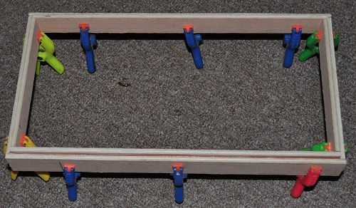
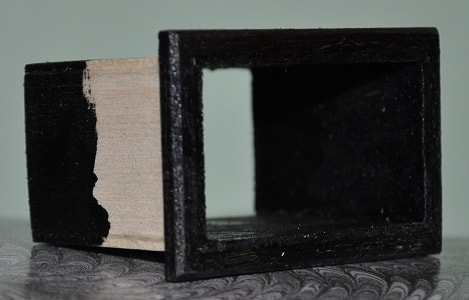
Glue the inner sides and top/bottom to the previous frame so the front edges of the inner frame is set back 5/16” from one edge of the outer frame as shown. This will be the front. Please note that I did not allow enough clearance for the inner frame to fit easily in the main cabinet and made adjustments to the inner frame with a router. To avoid this issue, I suggest adding a strip of thin poster board between the inner and outer frame to give adequate clearance. Something about .020-.030” should do. Even a cut up cereal box will do. This is not in the pictures. The rest of the door panel assembly stays the same.
|
|
Door Frame Front Door Frame Back
|
|
Door Frame Front Door Frame Back
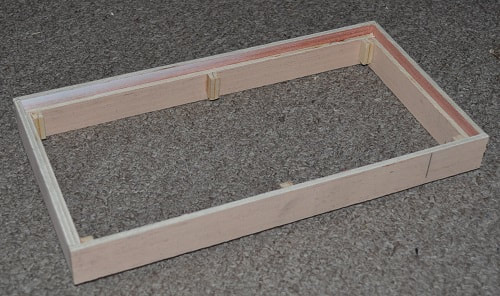
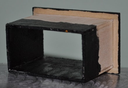
Install the four corner braces so the front end is flush with the front of the inner frame and falls 3/16” short at the back edge. This will allow the front panel to be 1/8” from the front edge of the door frame and the back panel will be flush with the back edge of the door frame. The simplest way I found to get the proper placement of these braces was to slip the back panel in place or use smaller scraps of the same thickness in each corner. Lay the assembly on its back on a flat surface and carefully glue the braces in place. If they are the proper length, then the front panel will be correctly recessed. As you can see from the above picture, I added the optional braces at the center point of each side more for the back panel than the front.
Carefully fit the door front and rear panel in place and secure with a #2 flat head screw in each corner drilling pilot holes first, as you did for the main cabinet, to keep from splitting the corner braces. DO NOT GLUE IN PLACE.
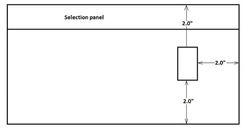
Mark out the location for the Pop Chute as described in the previous tutorial on building a non-opening machine also on Tutorial Page 3 and shown in the sketch below. The exact hole size will be dictated by the actual size of the finished chute but this gives you the location…centered right to left across the width of the cabinet and 2” from the bottom of the front panel.
Carefully fit the door front and rear panel in place and secure with a #2 flat head screw in each corner drilling pilot holes first, as you did for the main cabinet, to keep from splitting the corner braces. DO NOT GLUE IN PLACE.
Mark out the location for the Pop Chute as described in the previous tutorial on building a non-opening machine also on Tutorial Page 3 and shown in the sketch below. The exact hole size will be dictated by the actual size of the finished chute but this gives you the location…centered right to left across the width of the cabinet and 2” from the bottom of the front panel.
Before cutting the hole, I’d suggest fabricating the actual pop chute and make the hole fit it rather than the other way around.
POP CHUTE
If you can get your hands on some 1/16” hobby plywood, this will be easier than using 1/16” basswood. Any good hobby shop/craft store should have each. Or at least the basswood. My hobby shop was currently out of the plywood so I settled for the basswood I already had in my hobby wood supply.
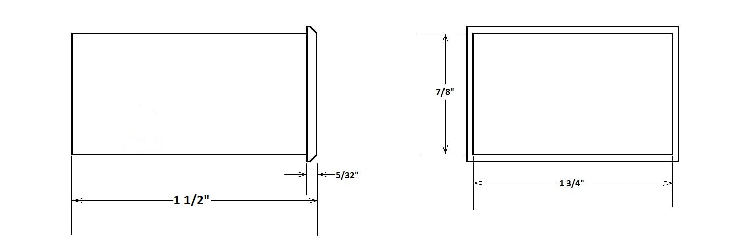
The chute consists of basically an open-ended box with a bezel around the open end that will fit through the hole and hide any rough fit. The internal dimensions of the chute, from the front should be near 1 ¾” wide and 7/8” high. The depth is up to you as it does not go anywhere but should have some depth to hold a can of pop. See the detailed sketch of mine…which is overkill.
If you can get your hands on some 1/16” hobby plywood, this will be easier than using 1/16” basswood. Any good hobby shop/craft store should have each. Or at least the basswood. My hobby shop was currently out of the plywood so I settled for the basswood I already had in my hobby wood supply.
The chute consists of basically an open-ended box with a bezel around the open end that will fit through the hole and hide any rough fit. The internal dimensions of the chute, from the front should be near 1 ¾” wide and 7/8” high. The depth is up to you as it does not go anywhere but should have some depth to hold a can of pop. See the detailed sketch of mine…which is overkill.
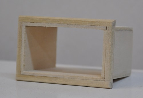
I removed the angled panel at the back for a reason but will most likely fabricate a “removable” one so it will look more like my first “non-opening” pop machine I built…or simply add a flap to the front as some machines have.
The bezel around the chute amounts to 5/32” square stock glued in place and sanded to an angle on the front edge. This works out quite well, I think.
The bezel around the chute amounts to 5/32” square stock glued in place and sanded to an angle on the front edge. This works out quite well, I think.
|
|
Once the pop chute is completed, accurately measure the width and height of the needed hole. Carefully mark and cut out the hole in the front panel and insert the pop chute but do not glue in yet.
SELECTION PANEL
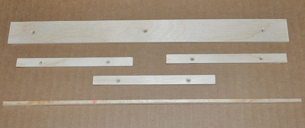
The panel for the buttons and such can be made now too. This can be simply a 1/16”-1/8” strip of wood (plywood is best) 1” wide and as long as the front panel is tall, or 11 5/8”. This should be sanded and sealed well and painted a gloss black.
The panel for the buttons and such can be made now too. This can be simply a 1/16”-1/8” strip of wood (plywood is best) 1” wide and as long as the front panel is tall, or 11 5/8”. This should be sanded and sealed well and painted a gloss black.
Start sanding and sealing of the front panel. The finish here is not as critical as the other sides as it will mostly be covered with a computer printed picture.
You can also seal and paint the pop chute, inside and the bezel, flat black. You can paint the bezel a gloss black if you like.
|
|
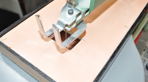
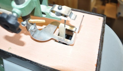
A scroll saw does a great job on cutting this out while cutting both panels at the same time quite accurately. If you do not have a scroll saw…I’d suggest cutting out the front panel ONLY and get the chute to fit this single panel well. Then do the best you can on the inner panel…cutting the hole a bit big if needed then add trim pieces of thin wood around the chute on the inner panel to clean up the fit.
After I cut and sanded the hole in the front panel, I assembled the door panel. Feeding the scroll saw blade through a drilled hole in the solid back panel, I started cutting out the back panel using the hole in the front panel as a guide. Notice I placed masking tape on the blade where it would contact the top panel without hindering cutting the bottom panel so I would not risk removing more material from the top, outer panel. This worked quite well though I was surprised that the hole in the back panel still ended up a bit over-sized. Which is fine and the gap will be covered by some trim pieces shown later on.
After I cut and sanded the hole in the front panel, I assembled the door panel. Feeding the scroll saw blade through a drilled hole in the solid back panel, I started cutting out the back panel using the hole in the front panel as a guide. Notice I placed masking tape on the blade where it would contact the top panel without hindering cutting the bottom panel so I would not risk removing more material from the top, outer panel. This worked quite well though I was surprised that the hole in the back panel still ended up a bit over-sized. Which is fine and the gap will be covered by some trim pieces shown later on.
|
|
Outer panel cut and starting Both panels cut for pop chute
on cutting back panel Notice the tape on the saw blade
on cutting back panel Notice the tape on the saw blade
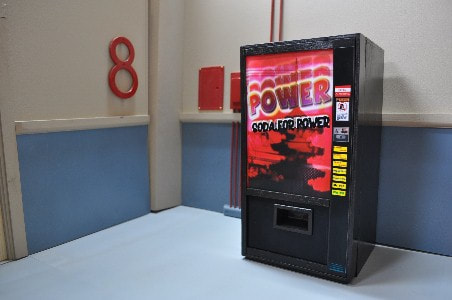
ADDING THE FRONT GRAPHIC
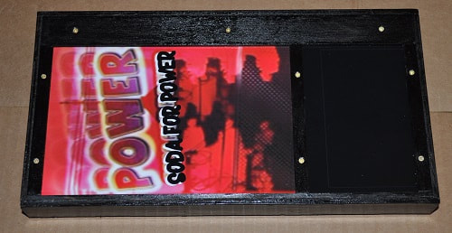
The graphic for the front is simply a computer printout on glossy photo paper. It takes some trial and error to get the graphic to print out to the right size but it is not hard with a fair image program. On the first pop machine, the graphic covered most of the front of the machine top to bottom. This one is based on a different machine requiring the graphic to stop above the pop chute. Once printed to size, I cut the photo paper to the correct width, leaving a white band down the right and left sides that will be covered by the trim as will the bands at the top and bottom. This also means you need a good paint job on the area around and below the pop chute or, do what I did and print out a section of gloss printer paper in black to cover this area.
The graphic for the front is simply a computer printout on glossy photo paper. It takes some trial and error to get the graphic to print out to the right size but it is not hard with a fair image program. On the first pop machine, the graphic covered most of the front of the machine top to bottom. This one is based on a different machine requiring the graphic to stop above the pop chute. Once printed to size, I cut the photo paper to the correct width, leaving a white band down the right and left sides that will be covered by the trim as will the bands at the top and bottom. This also means you need a good paint job on the area around and below the pop chute or, do what I did and print out a section of gloss printer paper in black to cover this area.
Selection panel and graphic trim pieces ready for paint
Place the finished graphic on the front panel (or card stock of equal thickness) Protect the left edge as described for the “non-opening” pop machine (wrapped in folded wax paper) Apply glue sparingly to the left side ONLY of the frail strip of painted (painted only on the top and right side) wood and position in place to hold down the left edge of the graphic. Heed the warnings of the previous tutorial for a pop machine about not pressing it too firmly against the graphic. Done properly, this will create a nice channel to hold the left edge of the graphic in place. And you do not want it TOO snug. The wax paper helps add to the width of the channel as well.
Place the finished graphic on the front panel (or card stock of equal thickness) Protect the left edge as described for the “non-opening” pop machine (wrapped in folded wax paper) Apply glue sparingly to the left side ONLY of the frail strip of painted (painted only on the top and right side) wood and position in place to hold down the left edge of the graphic. Heed the warnings of the previous tutorial for a pop machine about not pressing it too firmly against the graphic. Done properly, this will create a nice channel to hold the left edge of the graphic in place. And you do not want it TOO snug. The wax paper helps add to the width of the channel as well.
|
|
Once dry, you will need to remove the wax paper and reinsert the graphic. Lay the painted Selection panel along the right side and temporarily secured it to the front panel with three #2 flat head wood screws. One in the center and one at one inch from each end, centered on the width. You can also temporarily secure the top and center strip to hold the front graphic now with two #2 flat head screws each. If using a graphic to cover the bottom section, as I did, install the very bottom strip of wood.
All strips installed, still need to paint screw heads
With the center and very bottom strips installed, carefully cut out the hole for the pop chute through the graphic.
|
|
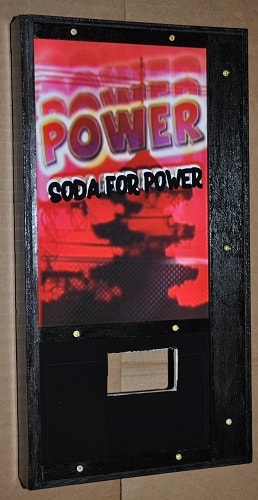
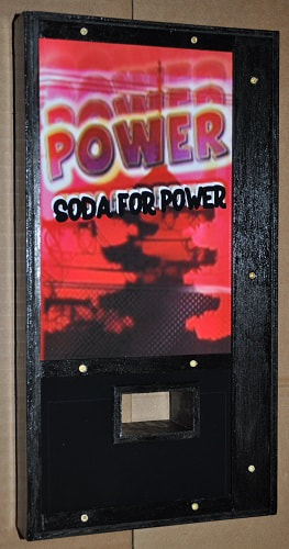
Chute hole cut Chute installed
HOW TO SECURE THE POP CHUTE
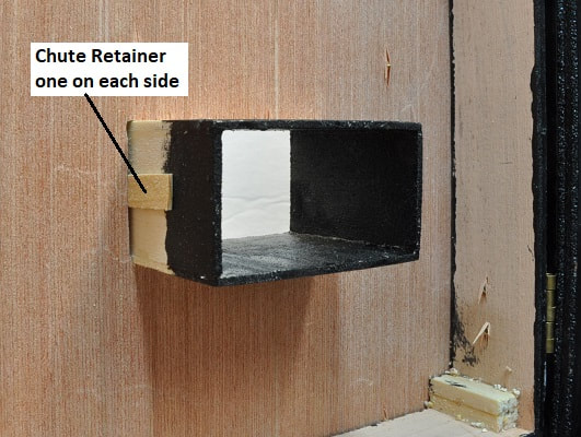
I know…sounds simple enough. But I like my projects to be serviceable in case the worst happens and some part needs repaired or repainted. I figured if I add a short piece of the material used to trim out the inside edges of the pop chute for the back panel with just a dot of glue (provided your fit of the pop chute in the hole is this close), it could be easily removed by slipping a single-edge razor blade between it and the chute. Suit yourself here but the picture below shows one of my two strips glued in place to one end…glued ONLY near the front panel. I made mine 5/8” long so they would never interfere with the fit of the back panel but would give me enough “unglued” area to get the razor blade started.
I know…sounds simple enough. But I like my projects to be serviceable in case the worst happens and some part needs repaired or repainted. I figured if I add a short piece of the material used to trim out the inside edges of the pop chute for the back panel with just a dot of glue (provided your fit of the pop chute in the hole is this close), it could be easily removed by slipping a single-edge razor blade between it and the chute. Suit yourself here but the picture below shows one of my two strips glued in place to one end…glued ONLY near the front panel. I made mine 5/8” long so they would never interfere with the fit of the back panel but would give me enough “unglued” area to get the razor blade started.
The back panel of the door panel may now be installed, secured with 6 more #2 flat head wood screws and trim added around the chute to cover the oversized hole. When gluing the trim strips in place, I would again suggest placing some card stock or very thin poster board around the pop chute and glue up to this so that if you do ever take the back panel off it will not be ridiculous getting it back on. I was going to simply paint this flat black until I noticed MANY pictures I came across had most of the area above the pop chute as galvanized steel. I settled for “aluminum” spray paint for this area with flat black paint used below.
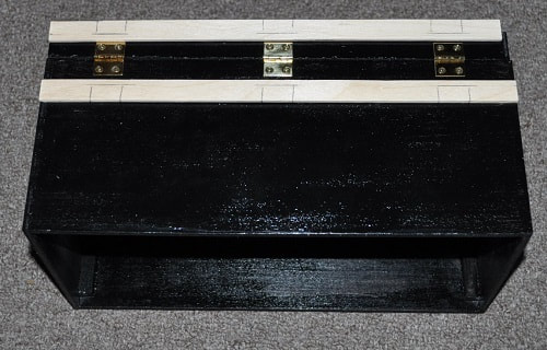
HINGE LOCATION AND INSTALLATION
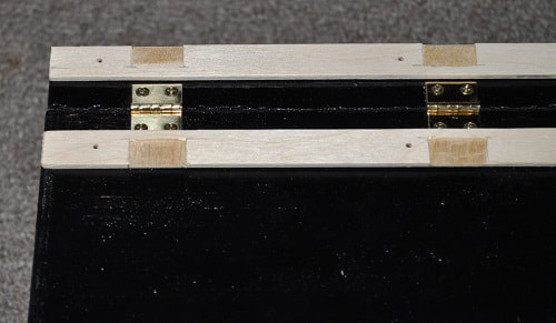
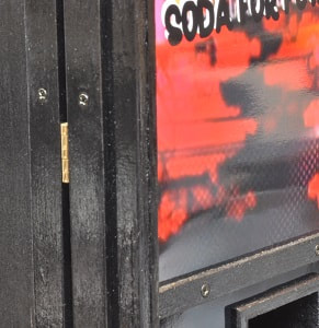
Install the three hinges along the left side (when facing the machine) with one in the center and one at 1/1/2” from each end. Mark the hinge locations on the two hinge cover plates and mill or router out clearance for the hinges.
Install the three hinges along the left side (when facing the machine) with one in the center and one at 1/1/2” from each end. Mark the hinge locations on the two hinge cover plates and mill or router out clearance for the hinges.
|
|
Hinge cover plates NOT notched Hinge Cover Plates notched
and upside down
and upside down
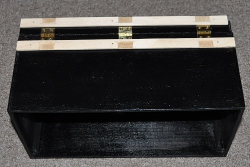
Paint hinge cover plates. Install these plates with three #2 flat head wood screws each. One screw just off center (to clear the hinge and one at 3/4” from each end.
|
|
|
HINGE COVER PLATES PAINTED AND INSTALLED
DOOR LATCH
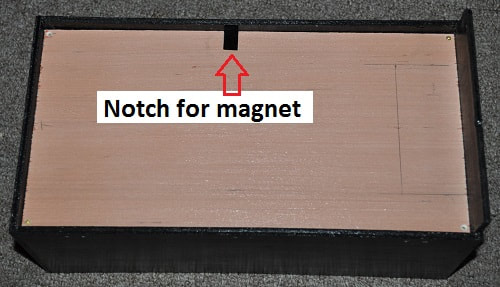
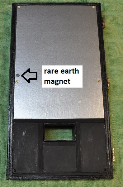
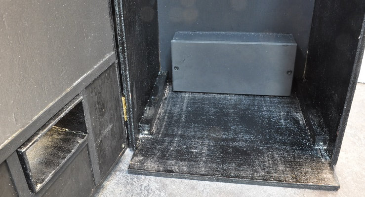
I was hoping that it would simply stay closed but the hinges are just very free swinging so some type of latch/lock is needed. As with the refrigerator and stove I built, I opted for a pair of rare earth magnets. One recessed into the door and one recessed into a block mounted to the inner right side wall. A lot of things need to be taken into consideration with this, or any, latch. As I wanted a removable inner panel with a picture of the pop awaiting sale, I had to notch this panel to accommodate the cabinet block.
I was hoping that it would simply stay closed but the hinges are just very free swinging so some type of latch/lock is needed. As with the refrigerator and stove I built, I opted for a pair of rare earth magnets. One recessed into the door and one recessed into a block mounted to the inner right side wall. A lot of things need to be taken into consideration with this, or any, latch. As I wanted a removable inner panel with a picture of the pop awaiting sale, I had to notch this panel to accommodate the cabinet block.
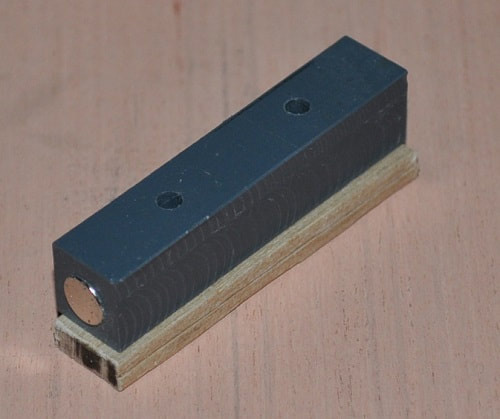
I fabricated a simple block for the cabinet magnet from a scrap of PVC scrap I had around but this could be anything. Had this been summer, I could have made it out of fiberglass and resin. It could be wood but it should indeed be a hardwood to hold the magnet well. Mine is 1 ¾” x 3/8” x 3/8”. I used my largest number set drill bit to bore a hole in the center of one end deep enough for the magnet. This hole is about .015” small so, using a bench vise, I forced the magnet into the hole. It is not coming out. I made a 3/16” thick spacer from a hardwood to place under the PVC block that will be glued to the inside of the cabinet to give more for the two mounting screws to hold into. Be careful these screws are not too long and break through to the outside. I didn’t have pan or round head screws of the required length so I did have to counter-bore the two holes in order to use ½” flat head screws but either is fine. And since I used the grey PVC block to hold the magnet, only the wood spacer needed painted.
The door magnet is simple enough. With the notch in the panel and the door installed and closed, work through the back of the machine to mark the location on the door through the notch. Reasonably close should count as these magnets are strong. Bore a hole just deep enough into the back door panel at this location to allow the second magnet to be pressed. WARNING-mind the polarity of these magnets or they will repel rather than attract.
With the door mounted and closed and the two screws just started into the wood spacer to hold it true to the block with the magnet, apply glue to the spacer then locate this assembly through the notch and just touching the door magnet. Let this glue dry completely then secure in place with the two #4 screws. Check the operation of the door. If all is well, remove the internal front panel block with the magnet from the cabinet and paint the spacer black. Once dry, reassemble.
ADDING THE SELECTION PANEL GRAPHIC
As I did on the previous pop machine…print out the assembled graphic onto letter size glossy photo paper, apply a length of double-sided carpet tape to the back side, trim with straightedge and single edged razor blade or hobby knife. Before removing the second strip from the tape, place it on the selection panel to get an idea of placement as it will be short. Divide the difference as you see fit. Mine ended up roughly split in the middle. And check fit down the sides as well. You may want to check one more time that the three flat head screws are truly flush or below the surface of the selection panel as they will show up boldly as a bump under that glossy graphic. Remove the backing strip from the graphic and CAREFULLY place it on the painted selection panel. With the tape I use, once it is on…it is NOT coming off without having to be replaced…so be careful.
As I did on the previous pop machine…print out the assembled graphic onto letter size glossy photo paper, apply a length of double-sided carpet tape to the back side, trim with straightedge and single edged razor blade or hobby knife. Before removing the second strip from the tape, place it on the selection panel to get an idea of placement as it will be short. Divide the difference as you see fit. Mine ended up roughly split in the middle. And check fit down the sides as well. You may want to check one more time that the three flat head screws are truly flush or below the surface of the selection panel as they will show up boldly as a bump under that glossy graphic. Remove the backing strip from the graphic and CAREFULLY place it on the painted selection panel. With the tape I use, once it is on…it is NOT coming off without having to be replaced…so be careful.
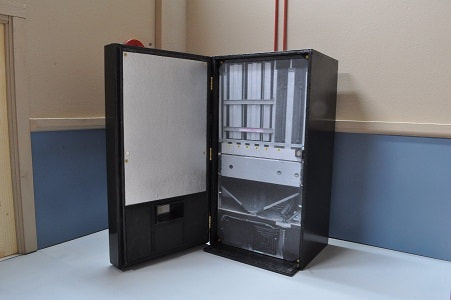
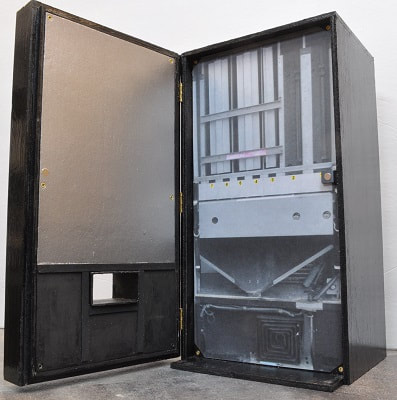
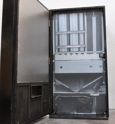
INTERNAL GRAPHIC (OPTIONAL)
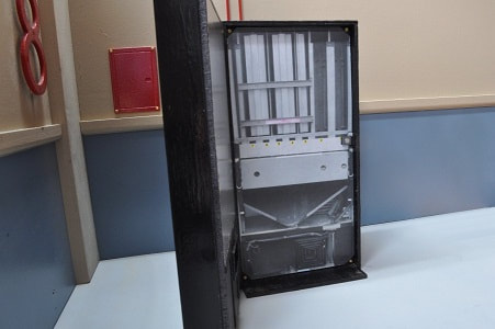
The opening door has two purposes. One will be revealed in my stories while the other is simply to have an internal graphic in place to make the machine look “right” when open. As I have yet to find anyone who will allow me to take a proper picture of a pop machine open, I did the best I could in searching the internet until I found the graphic of an empty machine…which is better than nothing…for now. This graphic will be replaced whenever I can get a picture of a full machine. The graphic I used was printed onto standard card stock as I did not want the gloss finish of photo paper. I applied the two sided tape to the back side and carefully applied it to the internal panel, notched it out for the magnet latch as well as the corner screw locations.
The opening door has two purposes. One will be revealed in my stories while the other is simply to have an internal graphic in place to make the machine look “right” when open. As I have yet to find anyone who will allow me to take a proper picture of a pop machine open, I did the best I could in searching the internet until I found the graphic of an empty machine…which is better than nothing…for now. This graphic will be replaced whenever I can get a picture of a full machine. The graphic I used was printed onto standard card stock as I did not want the gloss finish of photo paper. I applied the two sided tape to the back side and carefully applied it to the internal panel, notched it out for the magnet latch as well as the corner screw locations.
|
|
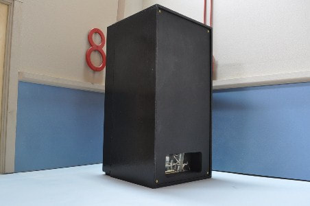
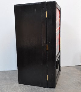
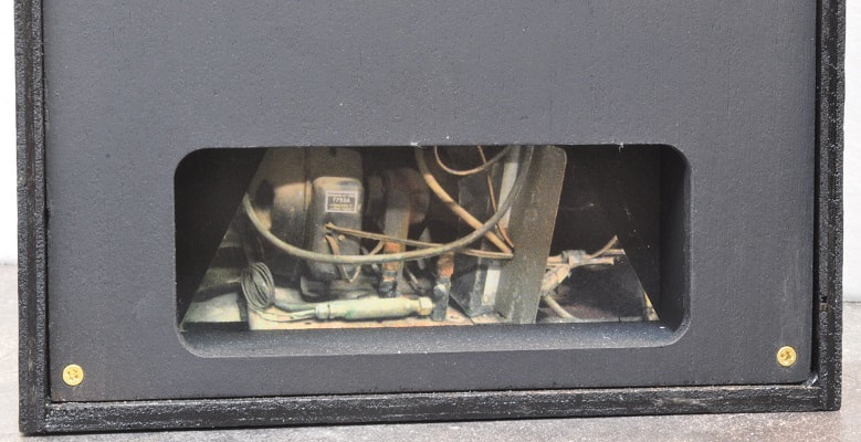
BACK OF POP MACHINE DETAIL (OPTIONAL)
I found most pop machines are NOT just flat on the back side so I added this detail to this version and may go back and add this to my first one in time.
In order to simulate the cooling system visible on the back of most machines, I added a small boxed in area to the bottom edge of the back panel that measures, on the inside, 1 ½” high by 4” wide and 1” deep. After painting it all flat black, I added a graphic of a cooling system from a pop machine to the back surface. It is simple enough to do and adds greatly to the realism in my opinion.
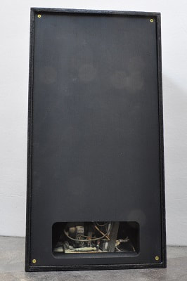
FULL VIEW OF BACK PANEL
|
|
CLOSEUP OF DETAIL VIEW OF DETAIL FROM INSIDE
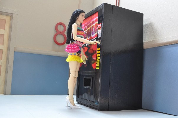
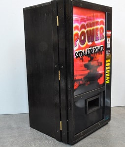
And here is the finished pop machine.