HOW TO MAKE A USPS MAILBOX
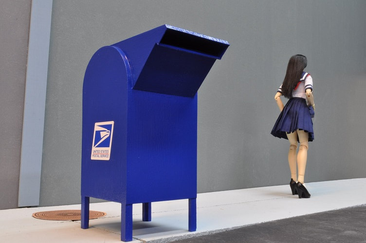
For a bit of Seattle Street front dressing, I thought a nice mailbox was in order.
SEE VERY END OF THIS TUTORIAL FOR A LINK THE SUBASSEMBLY FOR A PEDESTRIAN MAIL SLOT
If you plan to build your version WITH the Pedestrian Mail Slot, I would suggest building that subassembly first…with the two main side panels, as any errors made should be adjustable by making the cabinet a little wider or a little narrower once the subassembly is installed between the two main side panels.
If you plan to build your version WITH the Pedestrian Mail Slot, I would suggest building that subassembly first…with the two main side panels, as any errors made should be adjustable by making the cabinet a little wider or a little narrower once the subassembly is installed between the two main side panels.
PARTS LIST – MAIN CABINET
2 pcs just over 3 ¾” x 8” LUAN sides
2 pcs 3 3/8” x 3 3/4” LUAN bottom and mid brace
4 pcs 1 ½” x 1/8” x 3/16” pine front & back legs
2 pcs 3 5/16” x ¾” min. x ½” pine plywood seam brace
(I used some scraps that were close)
1/32 hobby grade plywood front/back/top skin & mail inlet
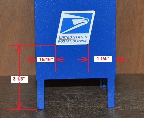
I first cut two pieces on Luan to just over 3 ¾” wide and just over 8” long. Carefully lining up one long side, I drive two ½” brads through them to hold them together. With these two pieces securely held together, cut the final width to 3 ¾” then carefully cut one end, ensuring that the cut is square to the long side. Mark the parts to ensure this end is used for the bottom. DO NOT REMOVE THE TWO BRADS. At the other end, draw a line at 8”. Locate the center, right and left, then use a compass to draw the 1 7/8” radius at this end as shown in the sketch.
2 pcs just over 3 ¾” x 8” LUAN sides
2 pcs 3 3/8” x 3 3/4” LUAN bottom and mid brace
4 pcs 1 ½” x 1/8” x 3/16” pine front & back legs
2 pcs 3 5/16” x ¾” min. x ½” pine plywood seam brace
(I used some scraps that were close)
1/32 hobby grade plywood front/back/top skin & mail inlet
I first cut two pieces on Luan to just over 3 ¾” wide and just over 8” long. Carefully lining up one long side, I drive two ½” brads through them to hold them together. With these two pieces securely held together, cut the final width to 3 ¾” then carefully cut one end, ensuring that the cut is square to the long side. Mark the parts to ensure this end is used for the bottom. DO NOT REMOVE THE TWO BRADS. At the other end, draw a line at 8”. Locate the center, right and left, then use a compass to draw the 1 7/8” radius at this end as shown in the sketch.
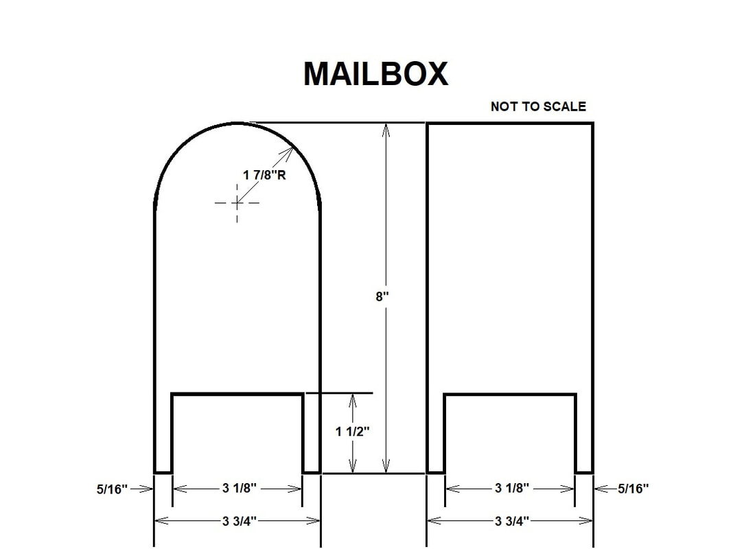
I used a scroll saw to remove the bulk of the excess material from the radius end then used a disc sander to sand the two pieces down to the compass line. Again, do not remove the two brads.
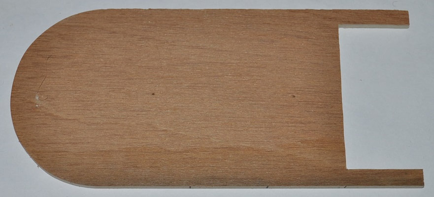
Mark out the two legs as shown in the sketch. I used my scroll saw again to carefully remove the material between the legs. If you use a fine blade here, with steady hands, there should be little need for much sanding this area.
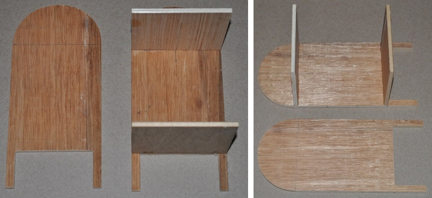
Now you may remove the two brads. You should have two identical sides as shown below.
Mark out the two legs as shown in the sketch. I used my scroll saw again to carefully remove the material between the legs. If you use a fine blade here, with steady hands, there should be little need for much sanding this area.
Now you may remove the two brads. You should have two identical sides as shown below.
From LUAN, cut two pieces 3 3/4” x 3 3/8” for the bottom panel and one mid support brace.
Glue one of the above pieces in the position of the bottom panel as shown. The bottom of this panel is flush with the leg opening.
Glue one of the above pieces in the position of the bottom panel as shown. The bottom of this panel is flush with the leg opening.
Once this is dry, glue the second support brace in position so the top of the panel is approximately 4 7/16”” above the bottom panel. That should put the top of this panel even with the center of the 1 7/8” radius and it will not interfere with bending the plywood around this curve.
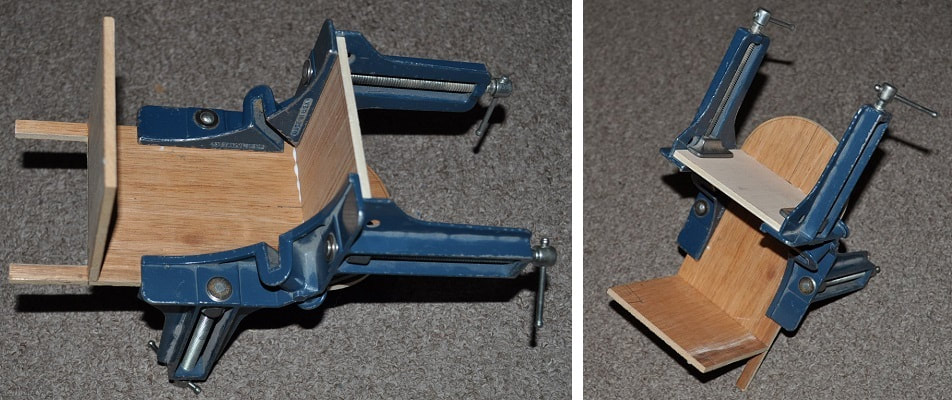
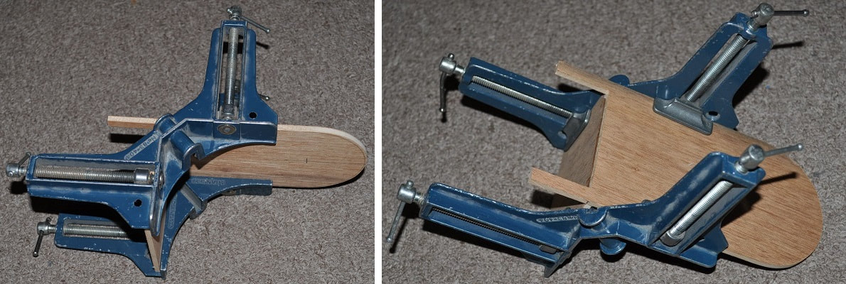
The Corner Clamps I used above are indispensable in constructions where you want joints to glue and dry together square to each other.
With the clamps removed, this is what you should now have.
The same clamps are unusable for attaching the other side due to the length of each leg of the clamp.
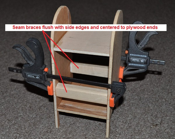
To secure the other side I used four 4” bar clamps to precisely hold the bottom panel in position against the side and to secure the brace panel against the side even with the center point of the top radius as before. Be watchful that both the bottom and brace panel stay flush with the front and back edges of the two sides.
The same clamps are unusable for attaching the other side due to the length of each leg of the clamp.
To secure the other side I used four 4” bar clamps to precisely hold the bottom panel in position against the side and to secure the brace panel against the side even with the center point of the top radius as before. Be watchful that both the bottom and brace panel stay flush with the front and back edges of the two sides.
Both sides glued and clamped to the bottom panel and brace panel.
Clamps removed from subassembly
On this build, I do not intend on making a working pedestrian door. This is, for now, simply a drive-by drop off box. And, for now, it is not intended to even be clearly seen from that side so…maybe next time. That being said, it is time to install the plywood “wrap” to the front, back and top. I bought a one foot by two foot sheet of 1/32” thick hobby grade plywood from our local lumber yard. It costs about $11.00. Cut two strip off the end a little more than 3 ¾” wide, so the grain is running crosswise…making it MUCH more flexible. This CAN be done on a table saw, if you have a jig to keep it from slipping under the rip fence…or you can find that any hobby plywood from 1/64” to 1/32” thick can be easily cut with a straight edge and a good single edge razor blade in a handle (like you would use for hanging wallpaper). Cutting this 1/32” thick plywood takes about 5-6 cuts, like when cutting really thick poster board.
Start by taking one of the two pieces of 1/32 plywood you just cut and locate and mark the center point along the factory cut edge and the center point of the top on one of the radii as shown below.
Start by taking one of the two pieces of 1/32 plywood you just cut and locate and mark the center point along the factory cut edge and the center point of the top on one of the radii as shown below.
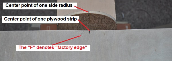
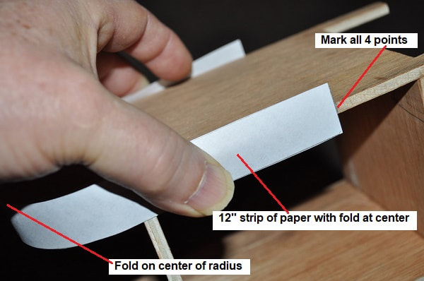
Locate and mark the four points down the sides where this 12” piece will end…six inches down from the top center following the curved edge as shown. A simple way to do this is to cut a narrow strip (1/2” – ¾” wide) diagonally from a piece of printer paper. Measure out and mark it at 12” and cut to this length. Fold it in half, place the fold line on the center mark of the radius then mark the ends on the side while holding it in place. This is the location of the next two braces. (SEE BELOW)
Glue and position the two plywood seam braces in place centered on these four plywood seam markings using care to keep them flush with the edges of the sides.
APPLYING THE PLYWOOD SKIN – FRONT/BACK AND TOP
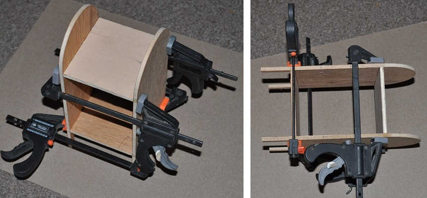
Apply glue to both side edges from the tops down to the center of and across the top half of the seam braces. Carefully line up the factory edge of the first plywood sheet with the edge of the side and its center mark on the center mark of the radius. Slowly force the plywood down over the two side radii until you can start adding clamps. Keep the “factory edge” as close to flush with the one side as possible. You may wanna try doing this once without the glue just to see what you are getting into…and how many clamps you will need.
Apply glue to both side edges from the tops down to the center of and across the top half of the seam braces. Carefully line up the factory edge of the first plywood sheet with the edge of the side and its center mark on the center mark of the radius. Slowly force the plywood down over the two side radii until you can start adding clamps. Keep the “factory edge” as close to flush with the one side as possible. You may wanna try doing this once without the glue just to see what you are getting into…and how many clamps you will need.
THIS SHOWS IT CLAMPED BUT NOT GLUED IN PLACE
I first found I was very comfortable with two clamps down the sides below the top radius, 4 in total, and two on each seam brace. NOTE: Remove any excess glue on the seam brace as it will interfere with the fit of the next two pieces.
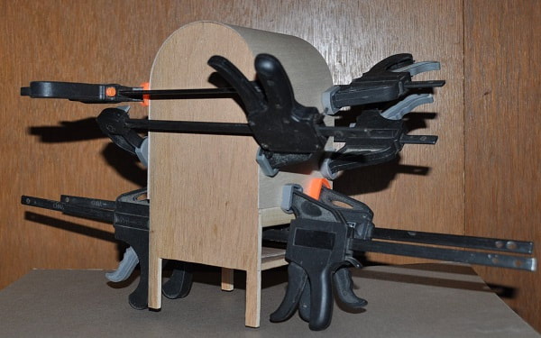
Now the assembly counts. Remove the clamps, apply the glue to the sides where the plywood will touch and start applying the clamps again watching that the factory edge of the plywood is VERY near, but NOT short of, the corner. This will make only ONE side being where the major trimming will take place. NOTE: Once the glue was applied and the plywood wrapped over the cabinet, I found I was more comfortable with THREE clamps down each side and THREE on each seam brace…not the two each I used when dry-fitting it above.
Now the assembly counts. Remove the clamps, apply the glue to the sides where the plywood will touch and start applying the clamps again watching that the factory edge of the plywood is VERY near, but NOT short of, the corner. This will make only ONE side being where the major trimming will take place. NOTE: Once the glue was applied and the plywood wrapped over the cabinet, I found I was more comfortable with THREE clamps down each side and THREE on each seam brace…not the two each I used when dry-fitting it above.
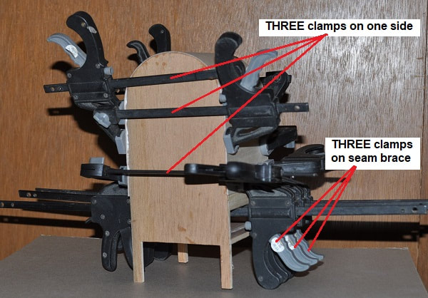
THIS SHOWS IT GLUED AND CLAMPED OVER THE RADIUS WITH 12 FOUR INCH BAR CLAMPS
Once dry, remove the clamps and recheck that there is NO excess glue on the exposed part of the seam brace. Clean off any if found. Scraping across it with a single edge razor blade should work well here.
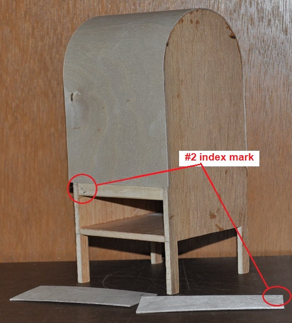
Cut two pieces from the other 1/32” thick plywood strip you cut earlier to finish the front and back from the seam brace to the bottom of the bottom panel. DO NOT COVER THE LEGS! It is unlikely that these two pieces will be identical…so cut them to length individually. After cutting each piece, I placed a # 1 in the corner of the first one and a #2 in a corner of the second and placed a matching number in the appropriate corner of the seam brace as shown below so I would not have to guess at how it “should” matchup.
Cut two pieces from the other 1/32” thick plywood strip you cut earlier to finish the front and back from the seam brace to the bottom of the bottom panel. DO NOT COVER THE LEGS! It is unlikely that these two pieces will be identical…so cut them to length individually. After cutting each piece, I placed a # 1 in the corner of the first one and a #2 in a corner of the second and placed a matching number in the appropriate corner of the seam brace as shown below so I would not have to guess at how it “should” matchup.
HERE IT IS WITH THE LAST TWO PIECES OF PLYWOOD FOR THE MAIN CABINET
Glue and clamp these last two panels in place.
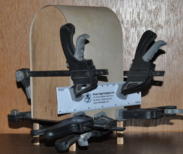
I glued these in place one at a time. Letting it dry between each to eliminate either one slipping during applying the clamps. I also placed a plastic rule under the clamps and over the seam between the plywood sheets to help smooth the joint.
I glued these in place one at a time. Letting it dry between each to eliminate either one slipping during applying the clamps. I also placed a plastic rule under the clamps and over the seam between the plywood sheets to help smooth the joint.
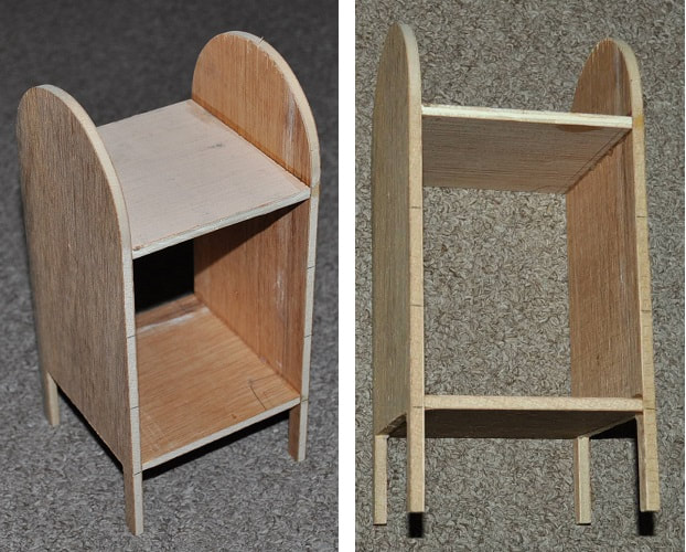
HERE IT IS WITH THE LAST TWO PIECES OF PLYWOOD INSTALLED TO THE MAIN CABINET
To remove the excess plywood down the corners…nothing works much better than a table mounted router with a bit made for trimming Formica or various veneers. But, with it being the middle of winter…and I failed to bring my router in the house last night to warm it up before using…I simply put a NEW piece of 100 grit sandpaper on my ¼-sheet hand sander to remove all excess in about 5 minutes. It would have taken longer than that to set up my router.
FINISH THE LEGS
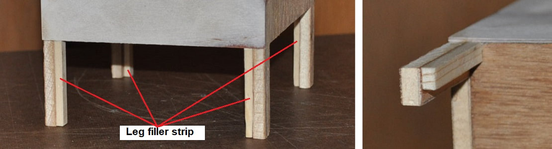
Cut four pieces of pine to 1 ½” x 1/8” x 3/16” to finish the front/back view of the legs. Glue and clamp in place.
Cut four pieces of pine to 1 ½” x 1/8” x 3/16” to finish the front/back view of the legs. Glue and clamp in place.
Lightly sand all sides as needed and fill and sand any brad holes or other flaws.
Set this assembly aside.
Set this assembly aside.
MAIL INLET CHUTE
PARTS LIST - MAIL INLET CHUTE
1/32 hobby grade plywood ALL sides
NOTE: ALL top, bottom and front sides will be 3 ¼” wide
and the sides will be glued flush to these pieces.
1/8” or 3/16” square pine corner reinforcing
(I used 3/16” square for the two lower corners
and 1/8” x 3/16” for the top corners)
Cut ALL pieces to sketch below to make a chute 3 ¼” wide (MAX)
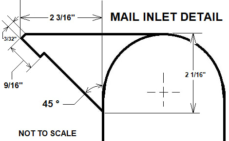
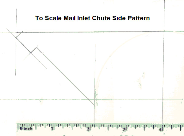
This can be downloaded and printed to size on cardstock to make a pattern if you like. And, if you print it with Windows Paint program, setting the percentage size at 254 % in print preferences should deliver a copy of the right size for a pattern.
MAIL INLET CHUTE ASSEMBLY
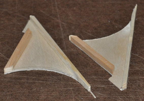
With all pieces cut and lightly sanded, add corner reinforcing strips as shown to these edges of the side pieces…they need to be flush with the side edges. I added a 45 degree angle to the front end of the piece glued to the lower edge so it will not be seen through the opening but still runs the full length of this edge. It is not necessary and may never be seen but why chance it. I also added a 45 degree angle to the front end of the top corner reinforcing strip to simply reduce sanding later. NOTE: I would not like trying to make the two side pieces with that 1 7/8” radius in them without a drum sander of some kind. I was actually going to make a true 3 ¾” diameter drum and wrap it with sandpaper for this project (I had it half way made) before I got brave and simply sanded this radius freehand with my 3” oscillating drum sander.
With all pieces cut and lightly sanded, add corner reinforcing strips as shown to these edges of the side pieces…they need to be flush with the side edges. I added a 45 degree angle to the front end of the piece glued to the lower edge so it will not be seen through the opening but still runs the full length of this edge. It is not necessary and may never be seen but why chance it. I also added a 45 degree angle to the front end of the top corner reinforcing strip to simply reduce sanding later. NOTE: I would not like trying to make the two side pieces with that 1 7/8” radius in them without a drum sander of some kind. I was actually going to make a true 3 ¾” diameter drum and wrap it with sandpaper for this project (I had it half way made) before I got brave and simply sanded this radius freehand with my 3” oscillating drum sander.
While the above pieces dry, I went ahead and glued the lower strip for the inlet to the bottom piece as they are perpendicular to each other and felt it would make things easier later.
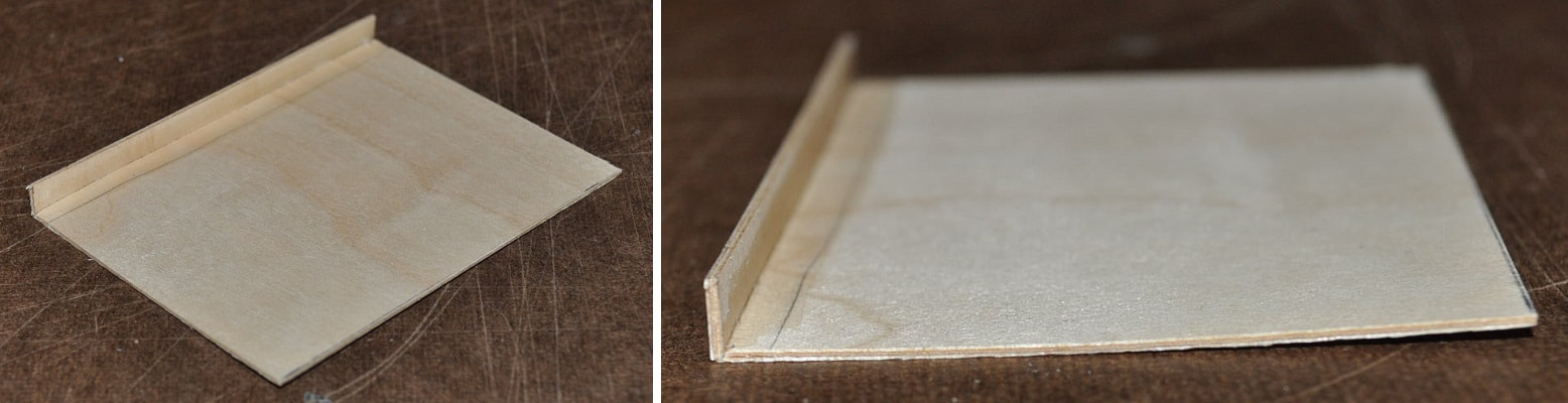
BOTTOM OF CHUTE WITH LOWER STRIP GLUED TO IT
GOOD masking tape can be indispensable in holding these next parts together as the glue dries. Some small plastic drafting squares can help too.
NOTE: When I say “GOOD MASKING TAPE”, or just “masking tape”, I mean tape of a reputable brand that typically costs more than a dollar a roll. LOL Seriously, when I buy masking tape, and I do on occasion buy the cheap stuff…but it is for a specific reason. I still, upon its first use, mark the inside of the cardboard center “GOOD, FAIR or POOR”. “GOOD” tape typically makes a LOT more noise when you are pulling it from the roll. I’m just sayin’ “Don’t use the cheap stuff here. OK…I’m off my soapbox.
NOTE: When I say “GOOD MASKING TAPE”, or just “masking tape”, I mean tape of a reputable brand that typically costs more than a dollar a roll. LOL Seriously, when I buy masking tape, and I do on occasion buy the cheap stuff…but it is for a specific reason. I still, upon its first use, mark the inside of the cardboard center “GOOD, FAIR or POOR”. “GOOD” tape typically makes a LOT more noise when you are pulling it from the roll. I’m just sayin’ “Don’t use the cheap stuff here. OK…I’m off my soapbox.
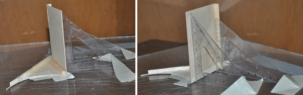
No clamps used here. Just glue, GOOD tape and two small drafting squares to attach first side
Once fully dry, use the same process to attach the second side.
Once fully dry, use the same process to attach the second side.
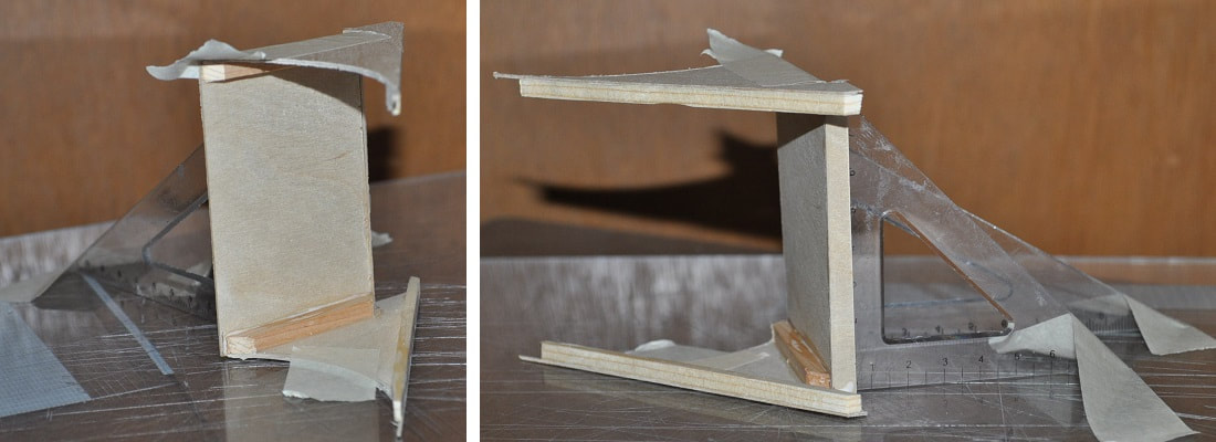
Now add the top panel to the chute. Gluing and taping as you go.
When dry, this structure should be quite rigid, allowing you to lightly sand the one end for the last narrow panel. Glue and tape that last narrow strip of plywood in place.
When dry, this structure should be quite rigid, allowing you to lightly sand the one end for the last narrow panel. Glue and tape that last narrow strip of plywood in place.
Once dry and the tape is removed, add extra glue, if desired, to the joints from inside.
The radius of this INLET CHUTE will most likely not match perfectly to the cabinet no matter how carefully you cut them unless you have this unit taped to the main cabinet during this assembly. I didn’t. I did end up touching up the radius again freehand against my oscillating drum sander, feathering the edges of the top and bottom pieces, and internal corner braces, in the process to better match the curvature. I wanted it to matchup as close as possible…rather than filling the gaps with plastic wood or glue.
Making a custom 3 ¾” drum sanding cylinder from scrap wood, covered it with 100 grit sandpaper then, with it turning rather slowly for this part is still a good idea if your hands are not overly steady.
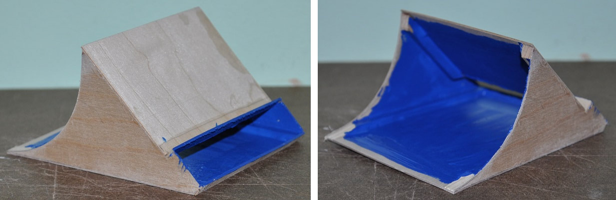
With all sides of the chute sanded and the radius joint fitting acceptably…position it on the cabinet. If all is well, this may be a good time to actually paint the inside of the INLET CHUTE. I painted it completely aside from falling just short of the edges that contact the main cabinet as I did not want the paint to interfere with the glue joint. Once this is installed to the main cabinet and dry, it is a small matter to reach inside the chute and paint any visible spots around the joint as well as the visible main cabinet interior. Much easier than painting the whole of the interior through the small opening. As it IS dark inside this chute, I did not bother to prime it first or even add a second coat as I felt the finish would be acceptable for an interior. I also painted the outer edge of the chute opening.
The radius of this INLET CHUTE will most likely not match perfectly to the cabinet no matter how carefully you cut them unless you have this unit taped to the main cabinet during this assembly. I didn’t. I did end up touching up the radius again freehand against my oscillating drum sander, feathering the edges of the top and bottom pieces, and internal corner braces, in the process to better match the curvature. I wanted it to matchup as close as possible…rather than filling the gaps with plastic wood or glue.
Making a custom 3 ¾” drum sanding cylinder from scrap wood, covered it with 100 grit sandpaper then, with it turning rather slowly for this part is still a good idea if your hands are not overly steady.
With all sides of the chute sanded and the radius joint fitting acceptably…position it on the cabinet. If all is well, this may be a good time to actually paint the inside of the INLET CHUTE. I painted it completely aside from falling just short of the edges that contact the main cabinet as I did not want the paint to interfere with the glue joint. Once this is installed to the main cabinet and dry, it is a small matter to reach inside the chute and paint any visible spots around the joint as well as the visible main cabinet interior. Much easier than painting the whole of the interior through the small opening. As it IS dark inside this chute, I did not bother to prime it first or even add a second coat as I felt the finish would be acceptable for an interior. I also painted the outer edge of the chute opening.
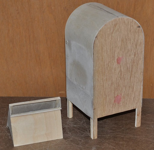
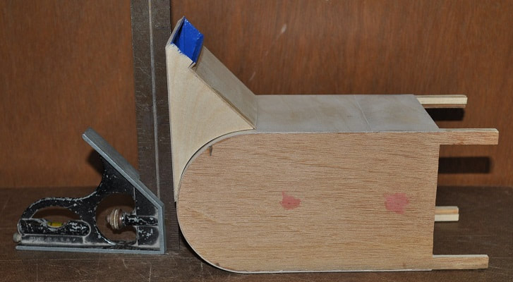
The back side of the main cabinet and the top of the mail inlet chute should make a right-angle when properly positioned together as shown below.
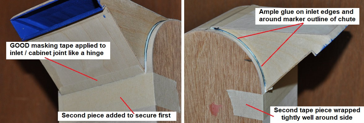
With the chute held firmly in place, this may take two people, apply a strip of GOOD masking tape to the lower edge of the chute/cabinet contact point as shown in the first of the three pictures below. I added a second piece of tape OVER the lower half of the first piece for extra measure, wrapping it an inch or more onto the two sides. Properly placed and smoothed out, this should make a very nice “hinge” to allow you to swing the chute away from the cabinet enough to easily add glue to all edges/surfaces and swing it back into its final position quickly and accurately.
With the newly applied “hinge tape” holding the chute in place, carefully trace around it on the other three sides so when you add glue to the chute’s edge, you can also add glue to this contact point as well on the main cabinet. A little glue in both locations it better than too much glue in either location as it will tend to run.
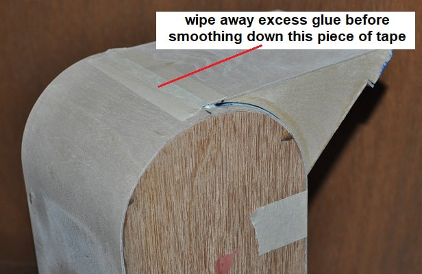
Fold back the chute and add glue to the edges and around, but inside the perimeter markings from the chute on the main cabinet. Swing the chute back into position, wiping away any excess glue from the joint at the top of the cabinet. Use masking tape to hold it in its final position. Now wipe away any excess glue along the radius joint.
With the newly applied “hinge tape” holding the chute in place, carefully trace around it on the other three sides so when you add glue to the chute’s edge, you can also add glue to this contact point as well on the main cabinet. A little glue in both locations it better than too much glue in either location as it will tend to run.
Fold back the chute and add glue to the edges and around, but inside the perimeter markings from the chute on the main cabinet. Swing the chute back into position, wiping away any excess glue from the joint at the top of the cabinet. Use masking tape to hold it in its final position. Now wipe away any excess glue along the radius joint.
Once fully dry, remove any masking tape and fill any gaps in the glue joint if needed. Typically the seam between the top of the chute and the top of the radius.
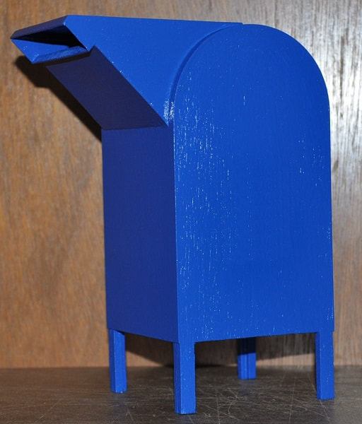
Apply one or two coats of primer with brush to hopefully hide any signs of the wood grain or seams. Then paint the entirety a proper blue. Apply two coats of proper blue paint to the entirety with a brush. If you prefer spray paints, one coat may be enough for the paint but I’d still recommend TWO good coats of primer…even if sprayed on. The paint I used is a Rust-oleum, gloss, Deep Blue premixed 8 ounce can of premium latex, #224423.
Apply one or two coats of primer with brush to hopefully hide any signs of the wood grain or seams. Then paint the entirety a proper blue. Apply two coats of proper blue paint to the entirety with a brush. If you prefer spray paints, one coat may be enough for the paint but I’d still recommend TWO good coats of primer…even if sprayed on. The paint I used is a Rust-oleum, gloss, Deep Blue premixed 8 ounce can of premium latex, #224423.
MAKING THE MAIN CABINET LABELS
I simply googled images of mailboxes until I came across a couple that were near enough profile views…cropped out their decal and painstakingly reconstructed the entirety of it in my favorite 25 year old image program until it looked like this.

|

|
Original cropped from image My Final Image
I did use Windows Paint program to make an image that had TWO of them to simplify printing…as I did need two. Printing them in Windows Paint program at 26% size should deliver an image about 1 3/16” high onto a 4” x 6” piece of glossy photo paper. Then to add a strip of two-sided carpet tape to the back was all that was needed before cutting them out.
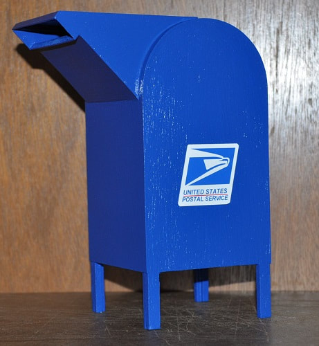
Here it is finished.
Please keep an eye out for this being featured in an episode of...
...iCarly:Five Years Later...
...iCarly:Five Years Later...
Below is the link to allow the addition of the Pedestrian Mail Slot.